Standard Shelter
Cod. +030221471 – Rel. 2.0 – April 01, 2003
33
19 MANAGING THE CONNECTION BETWEEN BOARDS (pLAN)
The pLAN network identifies a physical connection between the boards (pCO1 or pCO2) and the external terminals.
The address of the boards and the external terminals (not the built-in terminals) must be set for the correct operation of the pLAN.
If the same address is assigned to two objects in the network, the pLAN will not work!
19.1 ASSIGNING THE ADDRESSES
The pLAN addresses are set with binary logic by changing the position of a set of dipswitches located on the rear of the external terminals and on the
pCO2 boards (see figure below), and inside the electronic valve drivers. The operation must be performed when the devices are off. On the pCO1,
the address is numeric and is assigned using an external terminal.
For greater information refer to:
- pCO1 manual, Carel code: +030221840
- pCO2 manual, Carel code: +030221825
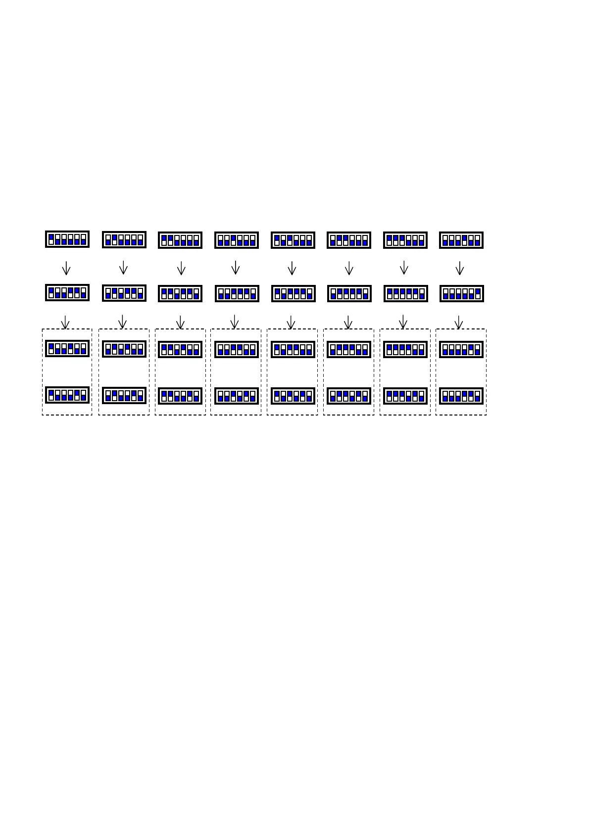
19.1.1 SETTING THE ADDRESS ON THE PCO2, EXTERNAL TERMINALS AND VALVE DRIVERS
The diagrams below show the addresses to be set on the pCO2 boards, on the external terminals and on the valve drivers. If pC01 boards are used,
refer to the following paragraph for the boards only; for the terminals and the drivers the diagrams below are still valid.
The main Menu screen on the terminals shows the address of the board connected in the bottom right corner. Using terminal address 32 all of the
boards can be controlled without requiring other terminals. The changeover between the boards is performed by simply pressing the Info button. The
shared terminal is the only solution that can be used to print the alarms and the parameters from all the boards.
In all the other program screens the address of the currently connected board can be displayed by pressing the Info button.
19.1.2 SETTING THE ADDRESS ON THE pCO1
Description of the operations to be performed for setting the pLAN address of the pC01 boards.
1. Switch the pCO1 board off and connect an external terminal with pLAN address “0”
2. Switch the pCO1 board on, while holding the Alarm + Up buttons on the terminal, until a screen is displayed
3. Once the screen appears, perform the operations indicated on the display, that is, enter the pLAN address (1,2,3….) using the Up and
Down buttons, and then confirm by pressing Enter
4. Switch the pCO1 board off
5. If necessary, assign the correct pLAN address to the external terminal
6. Switch the pCO1 board on
19.1.3 EXAMPLES OF USING THE pLAN NETWORKS
The pLAN network connection of the pC01 - pCO2 boards allows the following functions to be performed:
1. equalise the operating hours between the shelter units by rotating the spare unit (Standby)
2. start the spare unit if one of the other units shuts down due to a serious alarm or blackout
3. start the spare unit to compensate for excessive load
4. control up to 8 shelter units with just one external LCD terminal
5. print the alarms and the values read by the probes, using a shared external terminal
The pLAN network connection allows the configuration of a wide variety of systems. The main types of systems that can be developed are described
below, in order of complexity, with suggestions on how to perform the connections:
1. one or more independent shelters (board/boards with pLAN address 1 + external terminal/terminals with pLAN address 25)
2. two or more shelters and only one external terminal (boards with pLAN addresses 1-8 connected via RS485 using J11 connectors, terminal
with pLAN address 32 connected to one of the boards); this connection offers the possibility to perform the functions listed above
3. two or more shelters in a pLAN network, each with a private terminal (boards with pLAN addresses 1-8 connected via RS485 using J11
connectors, terminals with pLAN addresses 25-32 connected to the corresponding board); this connection offers the possibility to perform
the functions listed above
In the networks where the boards are connected in a pLAN network, the user can decide which units are involved in the Rotation function and which
not, thus creating a mixed network with some units that interact and others that are independent.
IMPORTANT: if only one board is used, it must have pLAN address 1, no electrical connection is required for the pLAN, and the external terminal,
if present, must have pLAN address 25.
Add.1 Add.2 Add.3 Add.4 Add.5 Add.6 Add.7 Add.8
Board 1 Board 2 Board 3 Board 4 Board 5 Board 6 Board 7 Board 8
Add.25 Add.26 Add.27 Add.28 Add.29 Add.30 Add.31 Add.32
Terminal 1 Terminal 2 Terminal 3 Terminal 4 Terminal 5 Terminal 6 Terminal 7 Terminal 8
Add.9 Add.10 Add.11 Add.12 Add.13 Add.14 Add.15 Add.16
Valve 1 Valve 3 Valve 5 Valve 7 Valve 9 Valve 11 Valve 13 Valve 15
Add.17 Add.18 Add.19 Add.20 Add.21 Add.22 Add.23 Add.24
Valve 2 Valve 4 Valve 6 Valve 8 Valve 10 Valve 12 Valve 14 Valve 16
 Loading...


