14
+050003290 - 1.4 - 29.09.2006
Connettori
Example of coding: PCO3CON***, see the following table for the description:
PCO3CON * * 0
0
= screw
1= spring
S= small
M= medium
L= large
Z= extra large N.O.
C= extra large N.C.
TECHNICAL SPECIFICATIONS
Mechanical characteristics
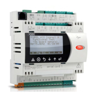
dimensions SMALL version fi tted on 13 DIN rail modules, 110 x 227.5 x 60 mm
MEDIUM, LARGE and EXTRALARGE version fi tted on 18 DIN rail modules, 110 x 315 x 60 mm
installation DIN rail
Plastic case
• fi tted on DIN rail according to DIN 43880 and CEI EN 50022 standards;
• material: technopolymer;
• fl ame retardancy: V0 (UL94) and 960°C (IEC 695);
• ball pressure test: 125°C;
• resistance to creeping current: ≥250 V;
• colour: grey RAL7035;
Electrical specifi cations
power supply (controller with terminal connected) 28 TO 36 Vdc +10/-20% and 24 Vac +10/-15% 50 to 60 HZ
maximum power input P= 15 W (24 Vdc power supply), P= 40 VA
(24 Vac)
terminal block with plug-in male/female connectors, max voltage 250 Vac;
cable cross-section: min. 0.5 mm
2
- max 2.5 mm
2
CPU H8S2320, 16 bit, 24 MHz
memory (FLASH MEMORY) 2+2 MB; in the extended versions further memory of 32 MB or higher
data memory (static RAM) 512 kB at 16 bit (296 kB BIOS; 216 application sw)
parameter data memory 13 kB at 16 bit (max. limit: 400,000 writes per memory location) and a
further 32 kB E
2
prom (not available to the pLAN)
working cycle duration (applications of average complexity) 0.2 s (typical)
clock with battery standard
Digital inputs
type optically-isolated
maximum number 8, 14, 18, respectively on the SMALL, MEDIUM and EXTRALARGE N.O and N.C., LARGE boards, according to
the combinations shown below:
optoinsulated input no. to 24 Vac
50/60 Hz or 24 Vdc
optoinsulated input no. to
24 Vac/Vdc or 230 Vac (50/60 Hz)
inputs
SMALL 8 none 8
MEDIUM/
EXTRALARGE
12 2 14
LARGE 14 4 18
classifi cation of the
measuring circuits
(CEI EN 61010-1)
Category I (J5, J7, J20) 24 Vac/Vdc
Category III (J8, J19) 230 Vac
WARNINGS: - 230 Vac 50/60 Hz (10/-15%);
- the two 230/24 Vac inputs present on J8 and J12 have the same common pole and consequently will be both
24 Vac/Vdc or both 230 Vac. Basic insulation between the two inputs;
- for DC inputs, connect the negative pole to the common terminal.
Note: separate as much as possible the probe and digital input signal cables from the cables carrying the inductive loads and the power
cables, to avoid possible electromagnetic disturbance.
 Loading...
