42
+050003290 - 1.4 - 29.09.2006
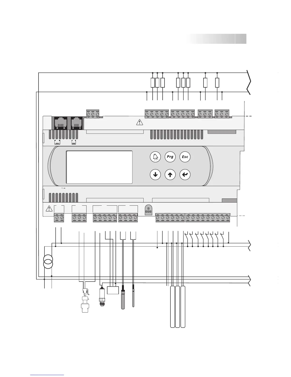
G
G0
230/24 Vac
M
OUT
+V
analog output 1 (0/10 Vdc)
analog output 2 (0/10 Vdc)
analog output 3 (0/10 Vdc)
analog output 4 (0/10 Vdc)
L
N
digital output 1
digital output 2
digital output 3
digital output 4
digital input 1
digital input 2
digital input 3
digital input 4
digital input 5
digital input 6
digital input 7
digital input 8
digital output 5
digital output 6
digital output 7
digital output 8
probe 1 (0/5 V)
probe 2 (4/20 mA)
probe 3
(0/1 Vdc or 4/20 mA)
probe 4 Carel NTC
probe 5 PT1000
service card
Rx-/Tx-
Rx+/Tx+
GND
C1
NO1
NO2
NO3
C1
C4
NO4
NO5
NO6
C4
C7
NO7
C7
NO8
C8
NC8
G
G0
B1
B2
B3
GND
+VDC
+Vterm
GND
+5 VREF
B4
BC4
B5
BC5
VG
VG0
Y1
Y2
Y3
Y4
ID1
ID2
ID3
ID4
ID5
ID6
ID7
ID8
IDC1
J1 J24 J2 J3
J10J9
field card serial card
input: 24 V / ; 50 to 60 Hz
max. power: 40 VA/15W
SMALL
EXAMPLE GENERAL DIAGRAM OF THE ELECTRICAL CONNECTIONS
 Loading...


