plug-in
Cod. +030221881 rel. 1.5 - 26/10/10
15
3.2.2 Special warnings
For the direct connection of the instruments and the layout and checking of the wiring, the following warnings must be carefully read
and the diagrams adhered to; errors in connection can cause danger to the safety of the user and damage the instruments and connected
components. Also remember that the units must be fitted with all the electromechanical safety devices required to ensure correct
operation and the complete safety of the user.
For the 12Vac versions, if the power supply available:
is mains power, a safety transformer is required (CAREL code TRA12VDE01 or TRA12VDE00) to guarantee the double
insulation between the power supply and the low voltage electronics inside. If required, the protective fuse placed in series with the
primary (32 mAT, for code TRA12VDE00) is indispensable. The connection between the transformer and the instrument must be as
short as possible;
is already low voltage, but not 12Vac, a suitably rated adapting transformer must be used: double insulation between primary
and secondary, and suitable surge features on the primary (2000V for applications in industrial environments).
is 12Vac, the instrument can be powered directly, evaluating the following conditions. The power line must not be connected to
the actuators and must not be near other connections which may cause high intensity disturbance. In case of doubt, and to guarantee
conformity to electromagnetic immunity standards, an insulating transformer, with the characteristics described in the previous point,
is recommended.
If more than one control with a 12Vac power supply is connected to the same transformer, the polarity of the wiring must be checked,
in the sense that each terminal of the transformer must be connected to the same terminal of all the controls. In this case, conformity to
the EMI standards must be evaluated by the manufacturer/installer.
3.2.3 General warnings – installation and connection environments
Avoid mounting the boards in environments with the following characteristics:
relative humidity over 90% or presence of condensation;
heavy vibrations or knocks;
exposure to continuous jets of water;
exposure to aggressive and polluting atmospheric agents (e.g.: sulphur and ammonia gases, saline mist, smoke) which may cause
corrosion and/or oxidation;
high magnetic and/or radio-frequency interference (thus avoid installation near transmitting antennae);
exposure to direct sunlight and atmospheric agents in general;
large and rapid fluctuations in ambient temperature;
environments where explosives or mixes of inflammable gases are present;
exposure to dust (formation of corrosive patina with possible oxidation and reduction of insulation);
These warnings must be followed for connection:
electrical power supply other than that prescribed may seriously damage the system;
use cable ends that are suitable for the terminals. Loosen each screw and insert the cable end, then tighten the screws. On completing
the operation, tug the cables lightly to check they are sufficiently tight;
separate the probe signal and digital input cables from inductive loads and power cables as much as possible, to avoid any electromagnetic
disturbance. Never lay power cables and probe cables in the same cable channels (including those for the electrical cables). Do not
install the probe cables in the immediate vicinity of power devices (contactors, thermo-magnetic devices or other);
reduce the length of the sensor cables as much as possible, and avoid spirals around power devices. The probes must be connected
using shielded cables (minimum cross-section for each lead: 0.5 mm
2
);
the probes can be installed up to a maximum distance of 100m from the control. To extend the distance of the probes, use cables with
a minimum cross-section of 1 mm², shielded where possible. In this case, the shield must be connected to the common of the probe.
Do not earth the other end of the shield (the sensor end);
only use IP67 probes as end defrost probes; place the probes with the vertical bulb upwards, so as to assist the drainage of any
condensation. Remember that the thermistor temperature probes (NTC or PTC) have no polarity, so the order of connection of the
ends is not important;
avoid direct contact with the internal electronic components.
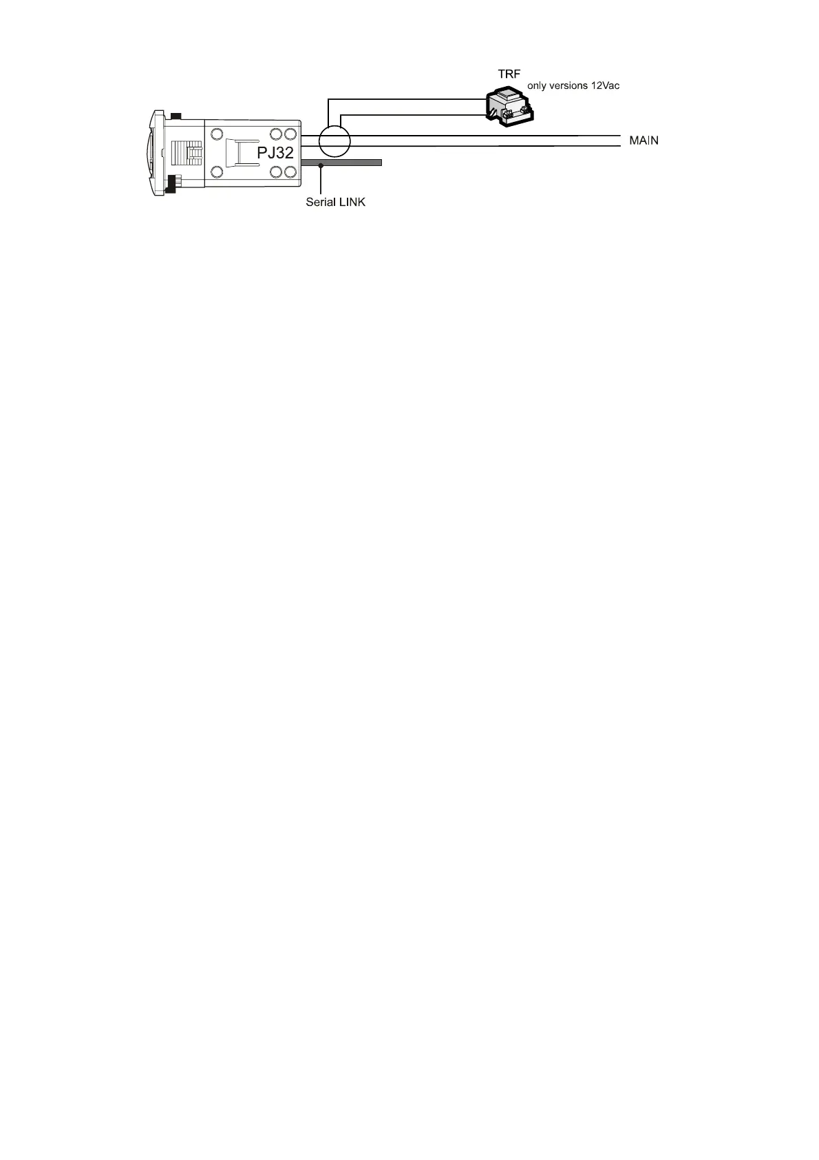
Wiring diagrams for multiple units, wiring examples for the serial connection of the instruments:
MAIN: mains power supply, 230 or 115Vac;
Fi
. 3.2.1.1
 Loading...