10
14. See Table 4 for normal operating ranges. Check these
characteristics hourly, recording readings in refrigeration
log. Refrigeration log should include all temperatures and
pressures mentioned above plus other machine history.
This important data helps service engineers determine
kind and frequency of service required. See your Carrier
Service Representative for refrigeration log forms (see
Fig. 2).
Table 4 — Normal Operating Ranges
* Compare refrigerant level with optimum level when machine is shut
down.
OPERATION
Manual Operation —
Control machine manually at the
PLC by setting guide vanes on MANUAL and adjusting guide
vane position. Operator must watch chilled water temperature
constantly when running machine in this manner.
Cold Weather Operation — Leaving condenser water
should be maintained at 65 F (18 C) minimum. Throttle con-
denser water flow or cycle cooling tower fans to suit.
Stop Machine
1. Check drive manufacturer's recommendations for adjust-
ments required before shutdown.
2. Push STOP button. Drive will immediately slow down
with a change in sound level. The compressor should
come to rest within a minute or two. Check drive and
gear, when used, to be sure lubrication is maintained.
3. After compressor shaft has stopped rotating, shut off con-
densing water, chilled water and oil pumps.
4. Shut off cooling water to compressor oil, gear oil. and tur-
bine oil coolers.
5. Shut off main steam (or gas) valve.
6. Open shutdown seal bleed valve (Fig. 3) after machine
completely stops rotating.
7. Leave controls energized for except for seasonal shut-
downs.
8. Leave oil separation tank heaters energized.
9. Isolate oil separation tank from the oil sump.
Extended Shutdown
1. Pump refrigerant into storage tank and valve it off to pre-
vent loss.
2
1
3
4
5
6
7
8
9
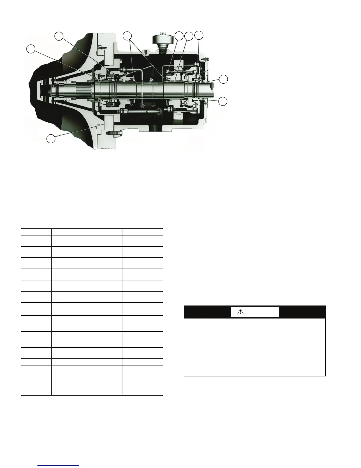
Fig. 3 — Compressor Details
LEGEND
1 — Shaft End Labyrinth, Seal End
2—Journal Bearing, Seal End
3—Journal Bearing Labyrinth,
Seal End, Thrust End
4—Seal Movement Switch
5—Journal Bearing, Thrust End
6—Shutdown Seal Bleed Line
(valve on opposite side)
7—Shaft End Labyrinth, Thrust End
8—Seal ring
9—Balancing Piston Labyrinth
a17-572
ITEM DESCRIPTION RANGE
1 Chilled Water Temperature
36-45 F
(2-7 C)
2 Condenser Entering Water
65-85 F
(18-29 C)
3 Compressor Supply Oil
110-120 F
(43-49 C)
4 Compressor Seal End Bearing
140-180 F
(60-82 C)
5
Compressor Drive End Journal
Bearing
140-180 F
(60-82 C)
6
Compressor Drive End Drive
Bearing
140-180 F
(60-82 C)
7 Condenser Temperature 105 F (41 C) Avg
8 Cooler Suction Temperature 28 F (-2 C) min
9 Seal Oil Supply Pressure
35 psi (241 kPa)
greater than item
10
10 Back of Seal Pressure
Approx. 2 lb (0.9
kg) higher than
suction pressure
11
Thrust Bearing Oil Supply Pres-
sure
18-22 psig
(124-152 kPa)
12 Cooler Refrigerant Level Varies with load*
13
Speeds
Maximum Continuous Speed
Nominal Speed
Compressor
(17DA7,17DA8)
6350, 5300 rpm
(106, 88 r/s)
5350, 4510 rpm
(89, 75 r/s)
CAUTION
Open seal shutdown valve only after machine comes to a
full stop. If this valve is opened before the machine is fully
stopped, the Teflon shutdown seal surface will be dam-
aged. A damaged seal will allow the full refrigerant charge
to be lost unless detected by the operator. If a hissing sound
is heard coming from the chamber or the odor of refriger-
ant is detected, immediately start the oil pump and inform
the servicing contractor. Leave the oil pump running until
the leak can be fixed.
 Loading...


