17
to the vacuum indicator only when taking a reading.
Leave the valve open for 3 minutes to allow the indicator
vacuum to equalize with the chiller vacuum.
3. If the entire chiller is to be dehydrated, open all isolation
valves (if present).
4. With the chiller ambient temperature at 60 F (15.6 C) or
higher, operate the vacuum pump until the manometer
reads 29.8 in. Hg vac, ref 30 in. bar. (0.1 psia)
(–100.61 kPa) or a vacuum indicator reads 35 F (1.7 C).
Operate the pump an additional 2 hours.
Do not apply a vacuum greater than 29.82 in. hg vac
(757.4 mm hg) or allow the temperature to drop below
33 F (0.5 C) on the wet bulb vacuum indicator. At this
temperature and pressure, isolated pockets of moisture
can turn into ice. The slow rate of evaporation (sublima-
tion) of ice at these low temperatures and pressures great-
ly increases dehydration time.
Filling the heat exchanger tubes with warm water (100 F
[38 C] or cooler) will warm any moisture clinging to the
tubes and thus will increase the evaporation rate. If the
waterbox covers are open warm air can be blown through
the tubes. Again observe the 100 F (38 C) limit.
5. Valve off the vacuum pump, stop the pump, and record
the instrument reading.
6. After a 2-hour wait, take another instrument reading. If
the reading has not changed, dehydration is complete. If
the reading indicates vacuum loss, repeat Steps 4 and 5.
7. If the reading continues to change after several attempts,
perform a leak test up to the maximum 160 psig
(1103 kPa) pressure. Locate and repair the leak, and
repeat dehydration.
REMOVING REFRIGERANT — Machines with refriger-
ant are usually provided with a storage tank and pumpout unit
to permit refrigerant removal when performing service work.
Refer to Pumpout System Operation section.
WATER TREATMENT — In hard water areas, the condens-
ing water system must be cleaned frequently (at least yearly) to
prevent a rise in condenser pressure. Proper water treatment
and cooling tower bleedoff reduces the amount of scaling and,
thereby, reduces frequency of tube cleaning required.
Since water conditions vary in all parts of the country, it is
recommended that a reliable water treatment specialist be con-
sulted and a sample of the condenser water tested to determine
the type of water treatment required.
CLEARANCES — Clearances for compressor components
shown in Fig. 4 and listed in Table 5 are a guide to be used
when checking or fitting a replacement part.
GEAR AND DRIVE — Refer to gear and drive manufactur-
er's instructions for maintenance requirements.
PUMPOUT SYSTEM — Refer to Carrier Service Instruc-
tions for 5F,H condensing units for maintenance.
Table 5 — Clearances
TIR — Total Indicator Reading
GENERAL DATA
Machine Nameplate —
The machine nameplate with
machine serial number and machine designation is located on
the safety panel. These numbers include information about the
machine. For example, 17DA81 indicates:
17 - Open-drive centrifugal refrigeration compressor
DA - Single-stage
81 - Compressor size
The overall assembly as well as each major component has
a serial number. When corresponding with your Carrier repre-
sentative, always give machine designation, machine serial
number, and component serial numbers.
Refrigerant Properties — Refrigerant is relatively
safe. The sweet-smelling vapor is nonflammable and nontoxic.
Heavy concentrations may cause dizziness, headache, and loss
of consciousness. When subjected to flame, refrigerant breaks
down into toxic gases. Avoid breathing fumes.
Refrigerant dissolves oils and destroys natural rubber and
all components containing rubber. Carefully selected neo-
prenes are safe to use.
Air or water floats on top of refrigerant in gas or liquid state
respectively. Being heavier than air, refrigerant will settle in all
low places. See Tables 6A and 6B for refrigerant temperature
vs pressure (saturated) relationships.
Relief Valve Assembly — The relief valve assembly is
located on the refrigerant storage tank. It prevents dangerous
high pressure from developing within the machine from fire or
any other reason.
System Components — The system components con-
sist of the following:
• Cooler - Heat exchanger which cools "brine" passing
through the tubes by evaporation of the refrigerant in which
tubes are immersed.
• Compressor - Machine which compresses the evaporated
refrigerant and discharges it to the condenser.
• Condenser - Heat exchanger which liquefies the evaporated
refrigerant discharged into it from the compressor.
• Purge Recovery Unit - A small condensing unit with separa-
tor which continuously extracts gas from the top of the con-
denser and purifies it by removing air which may be
present.
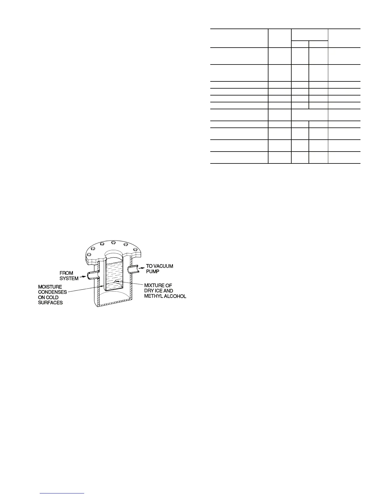
Fig. 7 — Dehydration Cold Trap
a19-661
DESCRIPTION
ITEM
(Fig. 4)
DIMENSION
(in.)
MEASURE
TYPE
Min Max
Shaft End Labyrinth
Seal End
Thrust End
1
8
.008
.001
.011
.003
Dia.
Dia.
Journal Bearing
Labyrinth
Seal and Thrust End
3 .005 .009 Dia.
Impeller Eye — .026 .034 Dia.
Balancing Piston 10 .032 .036 Dia.
Journal Bearings 2, 5 .0035 .0055 Dia.
Thrust Clearance — .008 .012 Axial
Thrust Disc Face
Runout
7 .0005 TIR Axial
Seal Ring 9 .0015 .004 Dia.
Seal Shoulder to Seal
Housing Face
—1
50
/
64
1
61
/
64
Axial
Shaft Movement
(Safety) Switch
Fig. 5 .014 .018 Fig. 5
Seal Movement
(Safety) Switch*
4 .020 .025 Axial
 Loading...


