7
The proportional band can be adjusted on the PLC to sta-
bilize the level if necessary.
3. Start the compressor. Observe the machine's operation for
15 to 20 minutes before increasing the load. During this
period, make the following checks and adjustments:
a. Check oil pressure.
b. Adjust water flow thru oil cooler so that bearing
temperatures stay between 150 and 170 F (65 and
77 C) approximately.
c. Watch bearing temperatures carefully. This is the
first time that the machine has been run under
refrigeration load. Bearing temperatures may level
off at some temperature slightly higher than 170 F
(77 C) listed above. This may be the normal stable
condition for this bearing. High thrust bearing tem-
perature will shut the machine down at 180 F
(82 C).
d. Watch the discharge temperature and if the temper-
ature climbs past 150 F (65.5 C), open the guide
vanes in small steps of 5% or less until the dis-
charge temperature starts to decrease.
4. Slowly open the guide vanes, by manual control, thus in-
creasing the load. Do not exceed the current rating of the
electric motor. Watch for other signs of overloading a tur-
bine or engine drive.
5. Add liquid refrigerant, trimming the charge off at the
point where the machine reaches design operating tem-
perature and pressure conditions.
6. Shut the machine off. When the refrigerant level settles
down, mark this optimum level on the sight glass. Main-
tain this shutdown level.
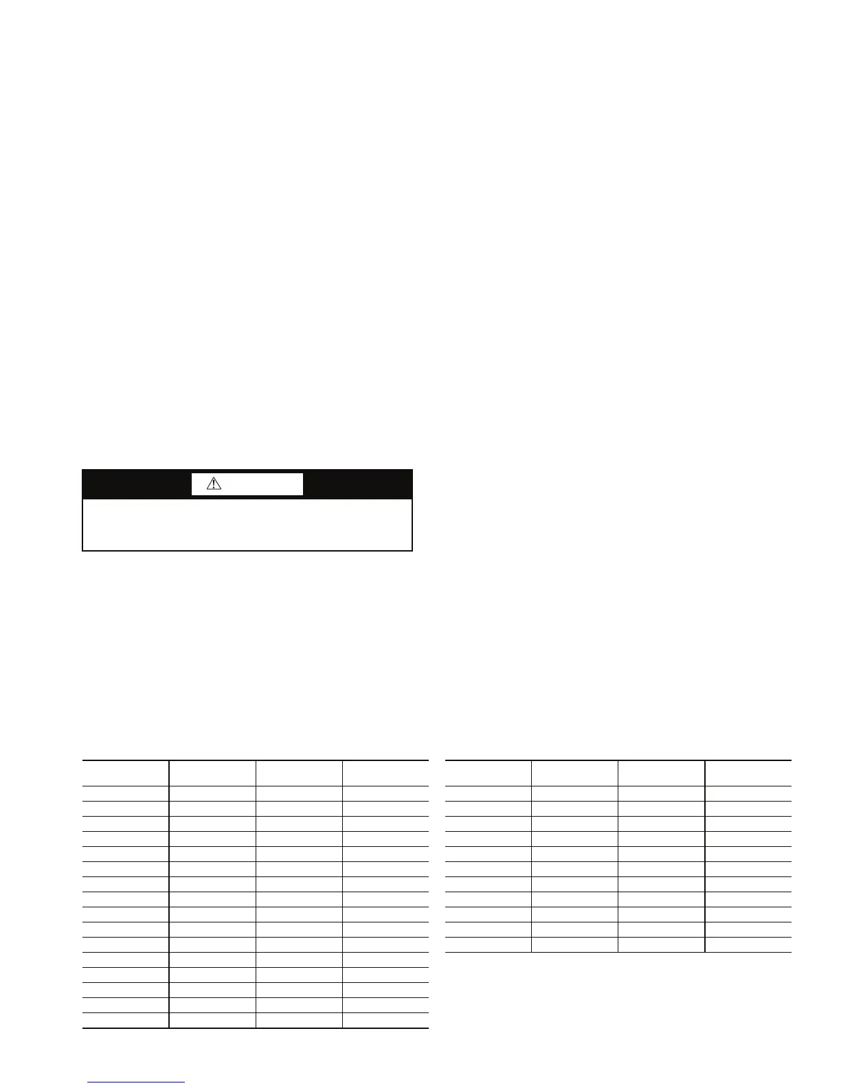
7. To determine the approximate refrigerant charge for the
machine, add the cooler charge to the applicable condens-
er charge as listed in Tables 3A and 3B.
Hot Alignment Check and Doweling — After the
machine has been running at about full load for 4 hours, its
components will have come up to steady state operating tem-
perature conditions and the final hot alignment check may be
made.
Realign component locations until angular and parallel
alignments are within coupling manufacturer's specified toler-
ances.
Dowel all equipment into place as soon as the hot alignment
check proves that the machine is within these running toleranc-
es. See Carrier Standard Service Techniques, Form SM-15,
Rev A, for these operations.
Operational Testing — When the chiller is in opera-
tion, and it is time to set the flows and confirm that the machine
is operating according to design conditions, a heat balance
must be determined. In brief, a heat balance is the sum of the
energy being absorbed by the cooler plus the energy supplied
through the driver (turbine, motor) compared with the energy
being discharged through the condenser.
Cooler Tons + Motor Tons = Condenser Tons
When these two items are equal it is certain that the readings
and measurements are accurate. The motor kW must be cor-
rected for motor efficiency and gear losses must be subtracted
from motor kW to get actual compressor input horsepower.
Motor kW is converted to equivalent tons by this formula:
Tons = kW / 3.515
Cooler and condenser tons: (for fresh water, specific heat
[sp ht] = 1 and specific gravity [sp gr] = 1)
Tons = (gpm * T * sp ht * sp gr) / 24
A perfect heat balance is 0, but this is practically impossible
to achieve. With laboratory quality instrumentation, less than a
2% heat balance at full load conditions should be achievable.
Greater than 5% should be regarded as very inaccurate and re-
quires further investigation of the start-up conditions.
Instruct Customer Operator — Ensure the opera-
tor(s) understand all operating and maintenance procedures.
Point out the various chiller parts and explain their function as
part of the complete system.
CONTROL PANEL
1. Internal safeties
2. Communication with chiller controls
3. Starter operational sequence
4. Current and voltage monitor operation
VFD
1. Detailed description of component, section, purpose, and
operation
2. Control section processor and access to screens
3. Procedures to switch from bypass to VFD operation (if
bypass equipped)
Table 3A — Typical 17DA Cooler and Condenser Charges (R-134a) (lb)
CAUTION
Excessive overcharge may cause liquid refrigerant carry-
over into the compressor, causing severe overload and pos-
sible compressor damage.
COOLER
SIZE
15-FT TUBES 18-FT TUBES 22-FT TUBES
CONDENSER
SIZE
15-FT TUBES 18-FT TUBES 22-FT TUBES
61 3,000 3,600 4,400 61 2,000 2,400 2,900
63 3,600 4,300 5,300 63 2,000 2,400 2,900
65 3,600 4,300 5,300 65 2,500 3,000 3,600
67 4,200 5,100 6,200 67 2,500 3,000 3,600
71 4,600 5,500 6,800 71 2,600 3,100 3,800
73 5,000 5,900 7,300 73 2,600 3,100 3,800
75 5,600 6,600 8,100 75 3,100 3,700 4,500
81 6,500 7,700 9,500 81 3,500 4,100 5,000
82 7,700 9,300 11,300 83 4,000 4,700 5,800
83 6,900 8,300 10,200 85 4,600 5,400 6,700
84 8,200 9,900 12,200 87 4,500 5,300 6,500
85 7,700 9,200 11,300
86 10,200 12,300 15,200
87 8,600 10,400 12,600
88 11,000 13,500 16,500
90 13,000 15,600 19,200
 Loading...


