5
Table 2 — Pumpout System Ratings
Charge Machine with Water — When the machine
has been proved leak tight and dry, it may be filled with water,
brine or other process fluid as the case may be. Vent all lines
and check for leaks.
It is advisable to install indicators on the coupling halves be-
tween the compressor and drive or gear to check for alignment
drift while charging with water and refrigerant. The weight of
these materials will always cause a shift in the position of the
machine components. Before and after indicator readings will
give a good clue to the direction final alignment should take.
Charge Machine with Oil — The 17DA chiller has an
integral lubrication system mounted on a common base with
the compressor. A parallel auxiliary oil pump system may also
be furnished. Charge the oil system with 35 gallons (132.5 L)
of oil, Carrier P/N PP23BZ106.
Refrigerant R-134a requires the use of polyolester oil. Poly-
olester oils have a different molecular structure proprietary to
each manufacturer and have property differences that may or
may not make them suitable for operation in the 17DA chiller.
Carrier supplied oil has been laboratory tested by Carrier and
has been field tested in the 17DA chiller.
Ensure that there is adequate lubrication prior to the opera-
tion of all drive line components. Check the gear and drive
manufacturer’s instructions for proper initial lubrication
procedure.
Oil pressure from the main pump is set to maintain a pres-
sure 35 psi (241 kPa) greater than the refrigerant pressure be-
hind the shaft seal. If the oil pressure differential across the seal
falls below 23 psid (158 kPa), the auxiliary oil pump will start.
Final Pre-Operation Alignment Check — Prior
to operating the compressor and speed increasing gear (if
used), coupling alignment and separation must be checked.
1. Ensure that coupling alignment is within coupling manu-
facturer's specified tolerances.
2. Refer to the coupling vendor’s drawing for hub separa-
tion tolerances.
3. When checking hub separation, electric motor shaft must
be in center position of shaft float or in magnetic center as
specified by the motor manufacturer.
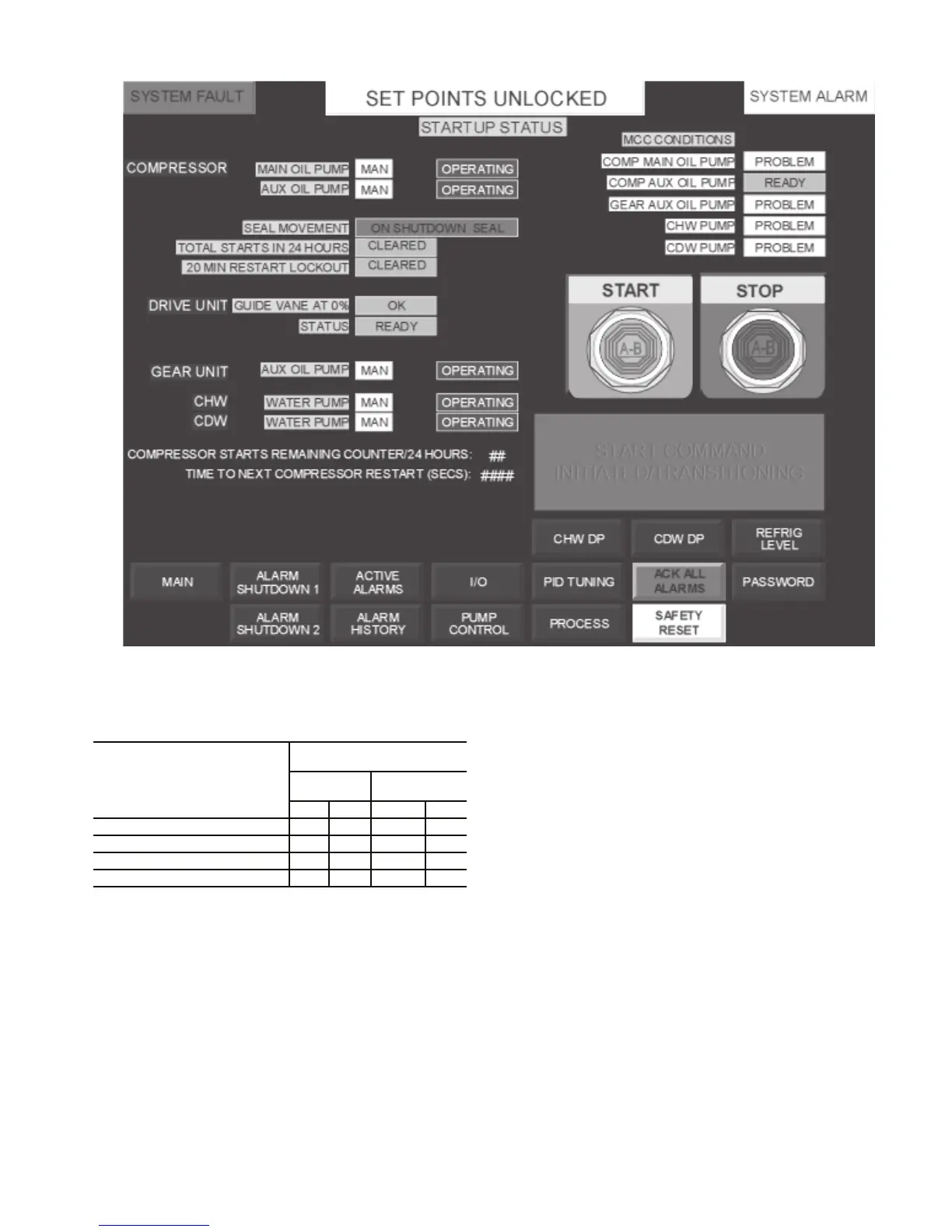
Fig. 1 — Typical PLC Screen on Control Panel
a17-578
PUMPOUT
SYSTEM
SETTING
SATURATED CONDITIONS
(R-134a)
Pressure
Maximum
Temperature
psig kPa F C
Normal Condensing Pressure 146 1007 110 43
Low-Pressure Cutout 31.5 217 36 2
High-Pressure Cutout 175 1207 121 49
Relief Valve 185 1276 125 52
 Loading...


