19
Auxiliary oil pump, if used, operates when seal oil and
back-of-seal oil pressure difference is less than 23 psi. Control
is located on machine safety panel.
Purge Cycle — See Fig. 6. Non-condensable gases, water
vapor, and refrigerant vapor pass from top of machine condens-
er through strainer (Item 3) and orifice (Item 4) to purge con-
densing chamber (Item 5). Water and refrigerant vapors are
condensed by cooling coil (Item 8) which is supplied with fil-
tered refrigerant (Item 3) through orifice (Item 4) in machine
condenser liquid line.
NOTE: Refrigerants HCFC-22 and HFC-134a hold a greater
percentage of water in the liquid state than in the vapor state.
As a result, HCPC-22 and HFC-134a refrigerants will not
release water in the purge. Use another method to detect water
in these refrigerants.
The condensed vapors fall in the condensing chamber (Item
5) and separate by gravity. Refrigerant collects in the lower
chamber (Item 9) and water in the upper chamber (Item 11). As
the refrigerant level in the lower chamber rises, float valve
(Item 9) opens and refrigerant flows through valve (Item 2) to
the cooler. Refrigerant vaporized in the cooling coil also re-
turns to the cooler.
Air and any other non-condensables accumulate in the con-
densing chamber. As the pressure in the chamber rises to ap-
proach within 8 psi of the chiller condenser pressure, the non-
condensables must be vented through the non-condensable
Vent valve (Item 7). Watch the condensing chamber gage (Item
6), and close the vent valve when the chamber pressure drops
to 16 psi below chiller condenser pressure.
12
13
14
11
10
9
8
7
65
15 16
17
4
18
PT
PT
PT
3
2
1
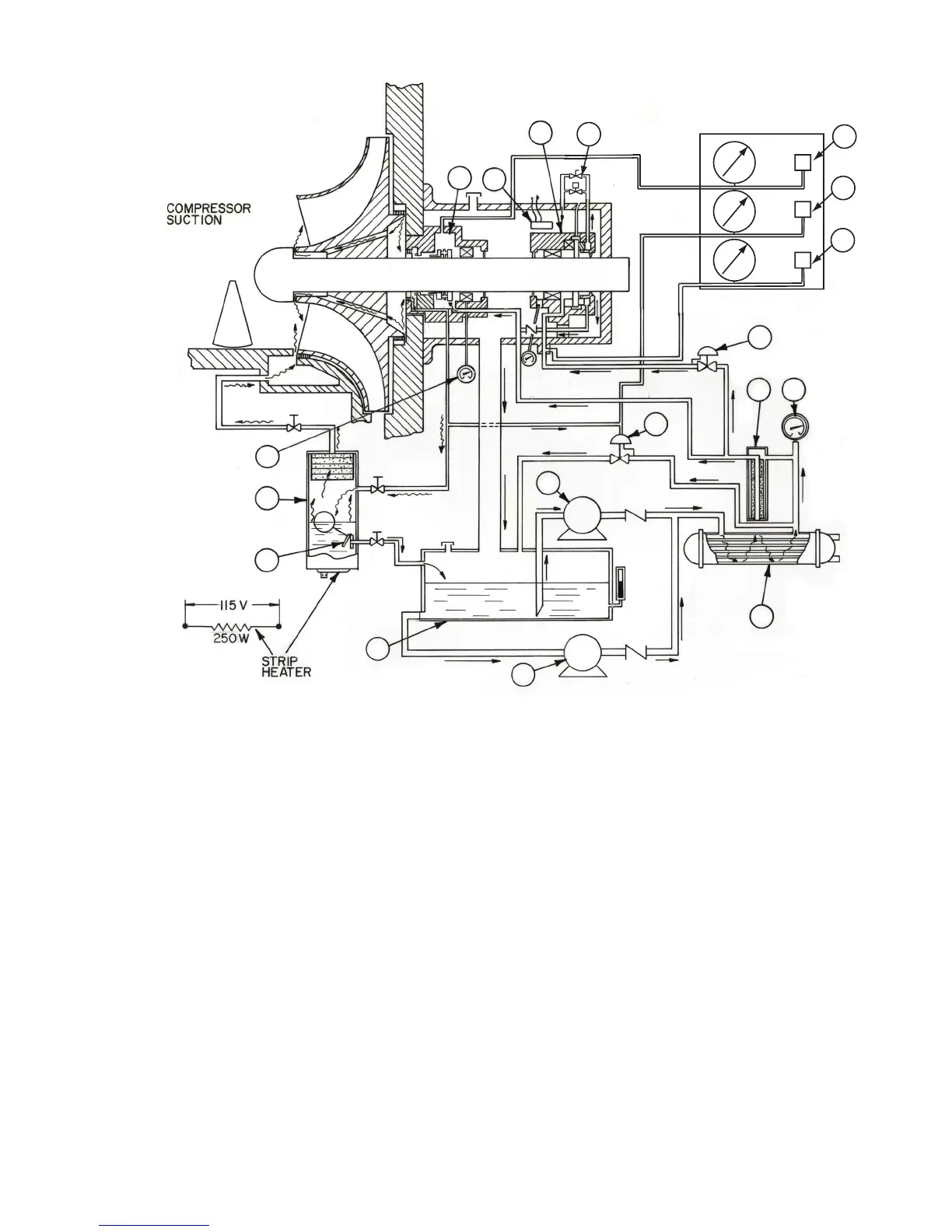
Fig. 9 — Schematic Oil Diagram
LEGEND
1 — Seal Oil Supply Pressure Transmitter 10 — Auxiliary Oil Pump
2—Back-of-Seal Oil Pressure Transmitter 11 — Oil Resevoir
3—Bearing Oil Supply Pressure Transmitter 12 — Seal Oil Return Float Valve
4—Low Pressure Regulator 13 — Oil/Refrigerant Separator
5—Oil Supply Temperature Gage 14 — Seal-End Journal Bearing Thermometer
6—Oil Filter 15 — Seal and Seal-End Journal Bearing
7—Oil Cooler 16 — Seal Movement Switch
8—Differental Pressure Regulator 17 — Thrust Bearing and Drive-End Journal Bearing
9—Main Oil Pump 18 — Shutdown Seal Automatic and Manual Bleed Valves
a17-576
 Loading...


