17
REFRIGERANT LINES
General refrigerant line sizing:
1 The outdoor units are shipped with a full charge of R410A
refrigerant. All charges, line sizing, and capacities are based
on runs of 25 ft. (7.6 m). For runs over 25 ft. (7.6 m), refer
to the Residential Long Line Guide.
2 Minimum refrigerant line length between the indoor and
outdoor units is 10 ft. (3 m).
3 Refri gerant lines shoul d not be buried in the ground. If it is
nece ssary to bury the lines , not more tha n 36--in (914 mm)
should be bur ied. Provi de a minim um 6--in (152 mm) ve rtical
rise to the se rvice valves to prevent refrigera nt migr at i on.
4 Both lines must be insulated. Use a minimum of 1/2--in.
(12.7 mm) thick insulation. Closed--cell insulation is
recommended in all long --line applications.
5 Specia l consi deration shoul d be given t o i solating
interconnecting tubing from the building structure. Isolate the
tubing so that vibrat i on or nois e does not transmi t into the
structure.
IMPORTANT: Both refrigerant lines must be insulated
separately.
S The following maximum lengths are allowed:
Table 13 – Maximum Refrigerant Line Lengths
Unit Size
Max Line
Length* ft(m
Max Elevation
(ID over OD)
ft(m)
Max
Elevation (OD
overID)ft(m)
18K-34K 250 (76.2) 65 (19.8) 200 (61)
Note: For lengths greater than 25 ft. (7.6 m), refer to the Residential
Long Line Guide.
*Maximum actual length not to exceed 200 ft. (61 m). Total equivalent
length accounts for losses due to elbows or fitting. See the Long Line
Guideline for details.
S The following are the piping sizes.
Table14–PipeSizes
Indoor Unit Outdoor Unit
Indoor Unit Tube
Sizes (in)
TXV Kit Tube
Sizes (in)
Outdoor Unit
Tube Size (in)
Liquid Vapo r Liquid Vapo r Liquid Vapo r
40MKCB18C----3
24AHA418
124ANS018
3/8
5/8
3/8
5/8
3/8
5/8
40MKCB34C----3
24AHA424
124ANS024
3/4 3/4 3/4
40MKCB34C----3
24AHA430
124ANS030
3/4 3/4 3/4
40MKCB34C----3
24AHA436
124ANS036
3/4 3/4 7/8
40MKQB34C-- --3
25HHA424
224ANS024
3/4 3/4 3/4
40MKQB34C-- --3
25HHA430
224ANS030
3/4 3/4 3/4
40MKQB34C-- --3
25HHA436
224ANS036
3/4 3/4 7/8
Note: Both lines need to be insulated using at least 1/2 inch closed
foam insulation.
Refrigerant Charge
Table 15 – Charge Requirements
System
Ty p e
Nominal
Capacity
kBTU/Hr
Outdoor Unit Indoor Unit
Charge to
Sub--cooling
Delta from
Rating Plate
Va l u e
Cooling
Only
018 24AHA418A003 124ANS018000 40MKCB18C----3 12
024 24AHA424A003 124ANS024000 40MKCB34C----3 12
030 24AHA430A003 124ANS030000 40MKCB34C----3 12
034 24AHA436A003/5/6 124ANS036000 40MKCB34C-- -- 3 8
Heat
Pump
024 25HHA424A003 224ANS024000 40MKCB34C----3 14
030 25HHA430A003 224ANS030000 40MKCB34C----3 11
034 25HHA436A003/5/6 224ANS036000 40MKCB34C-- -- 3 14
The above additional charge is required amount for line lengths up to
25 ft (7.6 m). F or line lengths exceeding 25 ft. (7.6 m), additional
charge will be required. Refer to the Residential Long Line Guide.
Metering Device
The 40MKC(Q)*C unit uses a TXV while the outdoor unit uses a
type B accurator. The cooling metering device is installed with the
indoor unit. The heating metering device is installed with the
outdoor unit. One metering device is required for the cooling only
system and two are required for the heat pump systems. Refer to
Table 16 for a breakdown of each unit’ s metering devices.
Table 16 – Metering Devices
System Size
kBTU/hr
Cooling Only Heat Pumps
40MKCB**C 40MKQB**C 25HHA4/224ANS
018 TXV - -
024 TXV TXV 0.049"
030 TXV TXV 0.055"
034 TXV TXV 0.063"
SYSTEM EVACUATION AND
CHARGING
UNIT DAMAGE HAZARD
Failure to follow this caution may result in equipment
damage or improper operation.
Never use the system compressor as a vacuum pump.
CAUTION
!
Refrigerant tubes and indoor coil should be evacuated using the
recommended deep vacuum method of 500 microns. The alternate
triple evacuation method may be used if the procedure outlined
below is followed. Always break a vacuum with dry nitrogen.
SYSTEM VACUUM AND CHARGE
Using Vacuum Pump
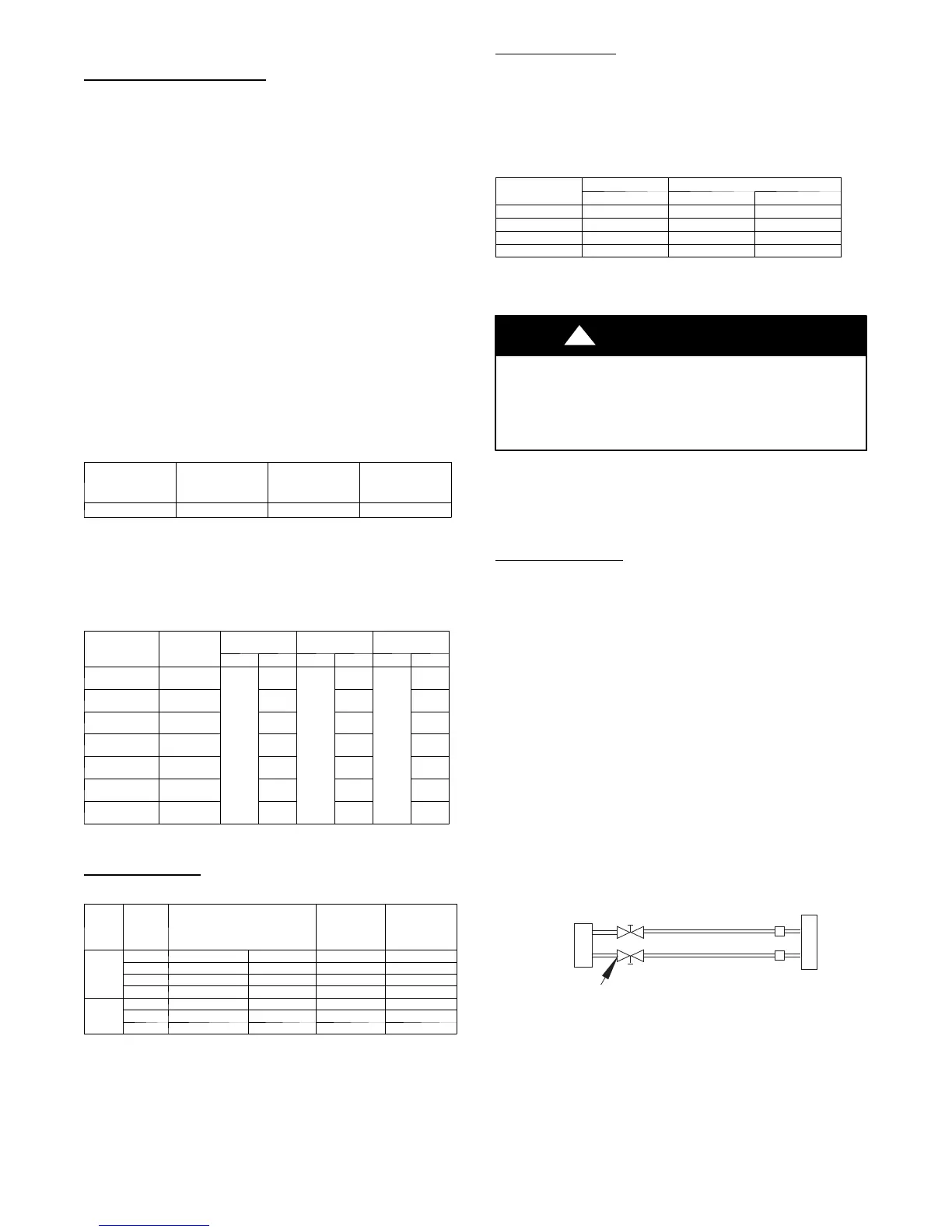
1 Completely tighten flare nuts A, B, C, D, connect manifold
gage charge hose to a charge port of the low side service
valve (see Fig. 17).
2 Connect charge hose to vacuum pump.
3 Fully open the low side of manifold gage (see Fig. 18).
4 Start the vacuum pump.
5 Evacuate using either deep vacuum or triple evacuation
method.
6 After evacuation is complete, fully close the low side of the
manifold gage and stop the vacuum pump operation.
7 The fact or y charge contained in the outdoor uni t i s good for up
to 25 f t . ( 8 m) of line l ength. For re frigera nt li nes longe r than
25 ft. (8 m), add cha rge, up to t he maximum allowa bl e length,
as specified in the residential Long Line Applicat i on Guide.
8 Disconnect charge hose from charge connection of the low
side service valve.
9 Fully open service valves B and A.
10 Securely tighten caps of service valves.
Outdoor Unit
Indoor Uni
Refrigerant
Service Valve
Low Side
High Side
A
B
C
D
A07360
Fig. 17 – Service Valve
 Loading...