8
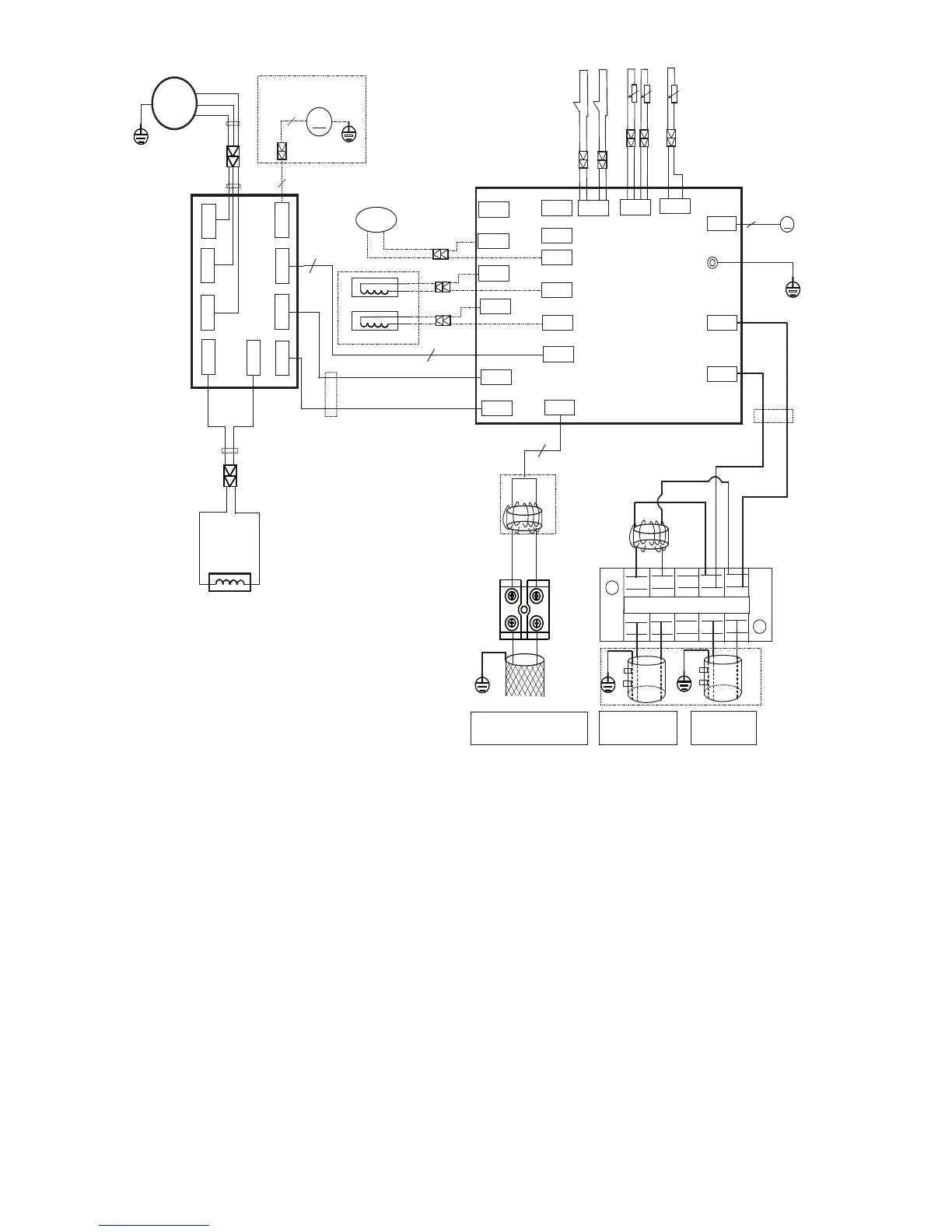
WIRING DIAGRAMS
COMP
FM1
MAIN BOARD
U
V
W
L
DRIVER BOARD
7
7
YELLOW
Applicable to the units
adopting DC motor only
CN52
CN6
SV
4-WAY1
BLUE
HEAT_D
HEAT_Y
OPTIONAL
3
BLACK
RED
BLUE
BLUE
YELLOW
BLACK
EEV
CN20
M
5
CN5
CN2
CN1
P-1
Y/G
L1
L2
(1)L1
(2)L2
RED
L-PRO
T3
T4
H-PRO
TP
CN33
CN8
CN9
CN41
CN42
CN43
CN3
CN22
CN4
CN10
CN7
CN44
CN40
BLUE
BLUE
BLUE
RED
BLACK
BLACK
RED
CN51
CN53
CN54
RED
CN55
CN19
3
Y/G
Y/G
U
V
W
BLUE
KCALBKCALB
RED
BLACK
MAIN POWER
SUPPLY
TO INDOOR UNIT
POWER SUPPLY
CN34
XT1
TO INDOOR COMM. BUS
XT2
S1
S2
NOTEφ
shielded wire.
Please use 2-core
YELLOW
GRAY
2
LAN
O
ITPO
LA
NOI
T
PO
OPTIONAL
Fig. 5 – Wiring Diagram Size 36K
OUTDOOR UNIT MAIN BOARD
CODE PART NAME
CN1~CN2 Input: 230VAC High voltage
CN5~CN6 Output: 230VAC High voltage
P-1 Connection to the earth
CN10~CN44 Output: 230VAC High voltage Chassis Crankcase Heater
CN4~CN40 Output: 230VAC High voltage Compressor Crankcase Heat
CN3~CN22 Output: 230VAC High voltage
CN43 Output: Pin3~Pin2, Pin4~Pin2 (230 VAC High voltage) For AC FAN
CN41~CN42 Output To AC FAN Capacitor
CN34 Output:-24VDC-24VDC
CN33 Input: Pin 1 (0-5VDC),Pin 2 (5VDC) Discharge Temperature Sensor
CN8 Input: Pin3, Pin4 (5VDC),Pin2 (0VDC),Pin1,Pin5 (0-5VDC) T3 & T4
CN9 Input: Pin2, Pin4 (0VDC),Pin1,Pin3 (0-5VDC) H/L Pressure Switch
CN20 Output: Pin1-Pin4: Pulse waveform(0-12VDC),Pin5, Pin6 (12VDC)
CN7 Output: Pin1 (12VDC),Pin2 (5VDC),Pin3 (EARTH)
 Loading...