21
REFRIGERANT LINES
General refrigerant line sizing:
1. The 38MVC/MVQ units are shipped with a full charge of
R410A refrigerant. All charges, line sizing, and capacities
are based on runs of 25 ft (7.6 m). For runs over 25 ft (7.6
m), consult long--line section on this page for proper charge
adjustments.
2. Refrigerant lines should not be buried in the ground. If it is
necessary to bury the lines, not more than 36--in (914 mm)
should be buried. Provide a minimum 6--in (152 mm)
vertical rise to the service valves to prevent refrigerant
migration.
3. Both lines must be insulated. Use a minimum of 1/2--in.
(12.7 mm) thick insulation. Closed--cell insulation is
recommended in all long--line applications.
4. Special consideration should be given to isolating
interconnecting tubing from the building structure. Isolate
the tubing so that vibration or noise is not transmitted into
the structure.
Long Line Applications, 38MVC Units:
1. A crankcase heater should be added for line lengths longer
than 25 ft (7.62 m) to prevent the migration of refrigerant to
the compressor during the “OFF” cycle.
2. A field fabricated wind baffle is recommended.
3. No change in line sizing is required.
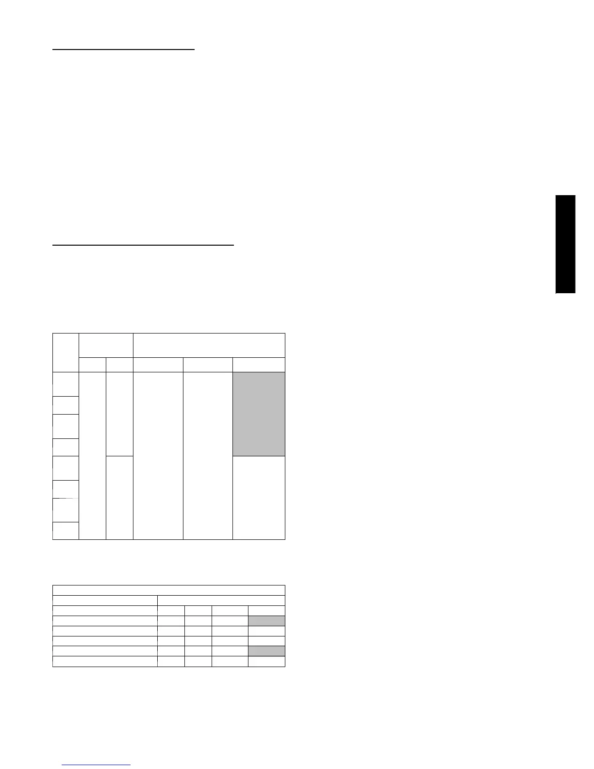
4. Add refrigerant per table below.
ADDITIONAL CHARGE TABLE
Unit
Size
Tot a l
Line Length,
ft
Additional Charge, oz.
ft (m)
Min. Max.
10 --- 25
(3.05 --- 7.62)
> 2 5 --- 6 5
(7.62 ---19.81)
> 6 5 --- 1 0 0
(19.81 ---30.48)
9K
cool
only
10
65
none
0.1 oz per
foot
9K
hp
12K
cool
only
12K
hp
18K
cool
only
100
0.3 oz. per
foot
18K
hp
24K
cool
only
24K
hp
5. Reduction in capacity due to long lines can be calculated
from the chart below.
CAPACITY LOSS
Capacity,%Loss
Line Length, ft
Cooling: 25 45 65 100
9&12KBTU/Hmodels 0% 2% 5%
18 & 24 KBTU/H models 0% 2% 4% 7%
Heating:
9&12KBTU/Hmodels 0% 7% 11%
18 & 24 KBTU/H models 0% 7% 11% 15%
WIRING
The main power is supplied to the outdoor unit. the field supplied
connecting cable from the outdoor unit to indoor unit consists of
four wires and provides the power for the indoor unit as well as the
communication signal between the outdoor unit and indoor unit.
For 9K and 12K units, all four wires are low voltage DC.
For 18K and 24K, two wires are high voltage AC power, one is
low voltage DC, and one is a ground wire.
CONTROL SYSTEM
The 40MVC/MVQ unit is equipped with a microprocessor controls
to operate the system and give optimum levels of comfort and
operating efficiency.
The main microprocessor is located in the control box of the fan
coil unit (there is one in the outdoor unit too) with thermistors
located in the fan coil inlet and on the indoor coil. These
thermistors monitor the system operation and control the operating
mode. To change the settings or the modes of operation, use the
factory supplied wireless remote control.
The 40MVC/MVQ unit has 5 operating modes:
S Fan Only
S Auto (heat pump models only)
S Heating (heat pump models only)
S Cooling
S Dehumidification (Dry)
FAN ONLY -- In Fan Only mode, the system filters and circulates
the room air without changing the room air temperature.
AUTO -- In Auto mode, the system will automatically select one of
the following operating modes: cooling, heating or fan only based
on the difference between the room temperature and the set point
temperature.
HEATING -- In the Heating mode, the system heats and filters
room air.
COOLING -- In Cooling mode, the system cools, dries and filters
room air.
DEHUMIDIFICATION (DRY) -- in Dehumidification (Dry)
mode, the system dries, filters and slightly cools room temperature.
This mode does not take place of a dehumidifier.
In addition to the above modes that are selected by using the
remote control, The unit can run in two other modes selected by
the manual button:
S EMERGENCY RUN
S TEST MODE
EMERGENCY mode is used when the remote control is
misplaced or the batteries in the remote control died. Pushing the
manual button once will put the unit in Auto mode with a
predetermined set point (76 _F/ 24.4 _C) .
TEST mode is used when a technician needs to diagnose the unit
for a malfunction. Pushing the manual button twice will put the
unit in test mode. The unit will run continuously for 30 min
regardless of the set point.
For more details on the sequence of operation please refer to the
service manual for those units.
WIRELESS REMOTE CONTROL
1. A wireless remote control is supplied for system operation
of all high--wall units.
2. Each battery--operated wireless (infrared) remote control
may be used to control more than one unit.
3. The wireless remote control has a range of 25 ft. (7.6 m).
38/40MVC, M VQ
 Loading...