Water connections
STANDARD version unit - Control panel
(See g. 35)
The control panel can be reached by opening the grille and removing
the metal covers using the 3 or 4 screws (See g. 36).
Connect the power cables to terminal box connectors in accordance
with the wiring diagram and tighten rmly (See g. 38-39-40).
IMPORTANT: Make ground connection prior to any other electrical
connections.
According to the installation instructions, all devices for •
disconnection from the power supply mains must have a contact
opening (4 mm) to allow total disconnection according to the
conditions provided for the overvoltage class III.
Fix the power supply cable under the corresponding cable holder. •
Make certain that the YELLOW/GREEN cable is stripped back further
than the others (See g. 37-43).
All the connecting cables to the fan coil unit and other accessories •
should be of the H05VV-F type, with PVC insulation and in compliance
with the EN60335-2-40 standard.
Unit with electric heaters
To power the unit using the electric heaters, connect the power
supply cable not directly to the electronic board as in the versions
without heaters, but using the terminal as shown in g. 41-42.
IMPORTANT for units with electric heaters;
The unit is equipped with two thermostats: one with automatic reset
and one with manual reset that can be reactivated.
Hot water and electric heaters can be used simultaneously only
if the Booster Heating function is enabled (control B + kit 42N9084).
Electrical connections
Water temperature sensor
The unit has a temperature sensor installed on the inlet of the water
pipe whic is used to connect the condensate drain pump only when
water temperature drops below a value for which pump connection is
requested.
Checking
On the unit startup, check if water ows correctly from the pump or
check the pipe slope and make sure the pipes are not obstructed.
To make water connections to the heat exchanger or the valves
use threaded joints and suitable materials that can ensure perfect
tightness.
The unit is provided with inlet and outlet female connections for
both 2 and 4 pipe models. An air bleed valve is also provided (g. 26),
which can be adjusted using a 8 mm wrench.
Motorized valve and control
The unit control circuit only allows opening of the motorized valve •
when the fan motor is working.
When the thermostat asks for cooling, outlet 1 of terminal TB3 on •
the electronic board is powered at 230V (and the corresponding
chilled water valve is energized). When the thermostat asks for
heating, outlet 2 of terminal TB3 on the electronic board is powered
at 230V (and the corresponding hot water valve or electric heater is
energized).
The control circuit ensures that the condensate discharge pump •
works continuously while the thermostat, asking for cooling, keeps
the cold water regulating valve open.
WARNING : The valve is not only necessary to control the room
temperature, but also to stop the cold water ow to the coil in
case of an abnormal condensing water level rise in the drain pan.
If there is an abnormal condensing water rise in the drain pan (for •
example: possible defective drain, pump malfunction, fan motor not
working) causing the opening of the oat switch contact (FS), the
control circuit either operates the condensate drain pump, or at the
same time closes the regulating valve, stopping the cold water ow
towards the coil and avoiding further condensation.
Control
The water ow has to be controlled:
by installing the motorized thermo-electric valves supplied as •
accessory
or
by installing motorized eld supplied valves.•
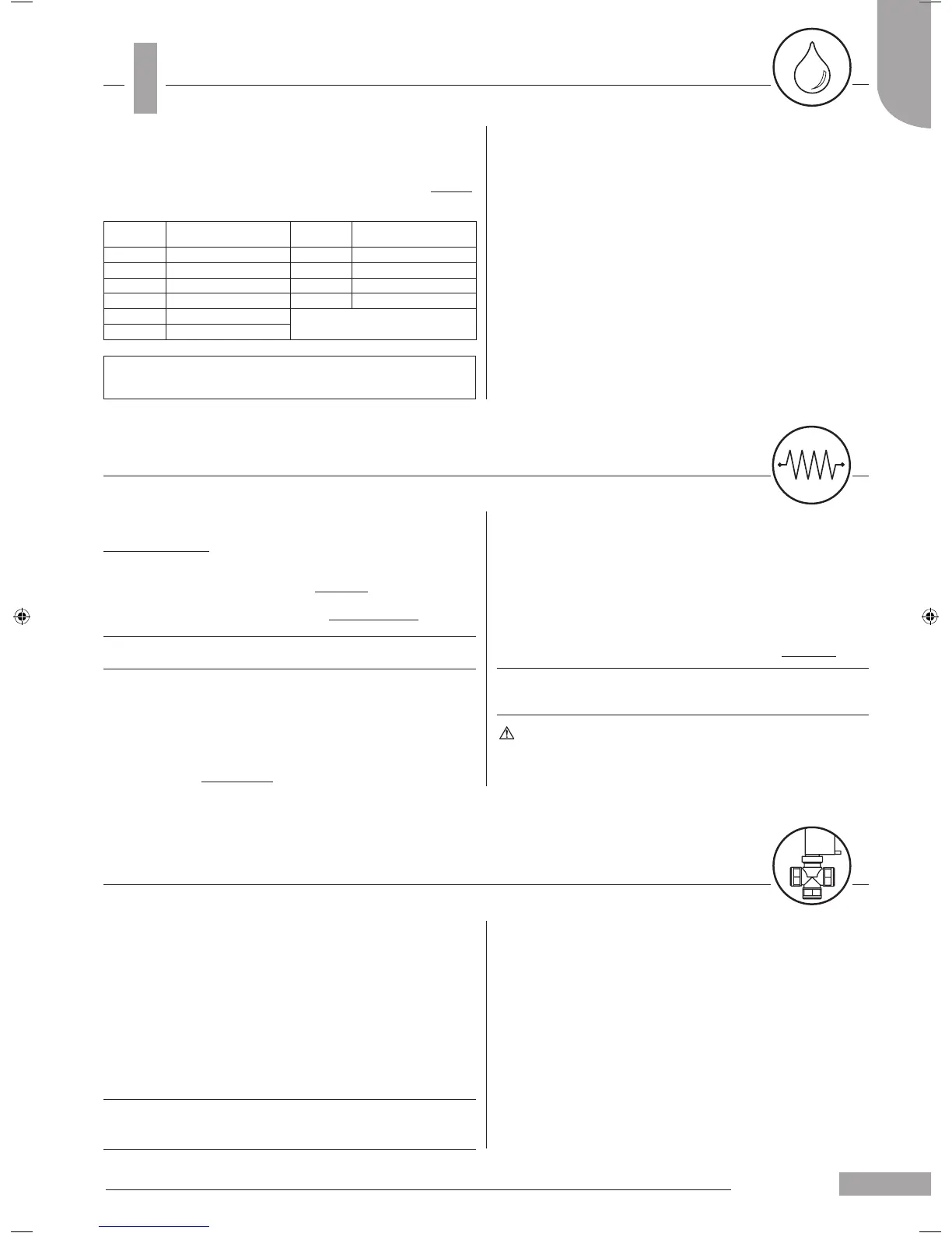
Models
Connections
dimension (Ø)
Models
Connections
dimension (Ø)
004 3/4" 012 1"
008 3/4" 016 1"
010 3/4" 020 1"
004* 1/2" 020* 3/4"
008* 1/2"
*Hot water circuits, four-pipe
version
010* 1/2"
To drain the unit completely, refer to “SYSTEM DRAINAGE” in the
Maintenance section.
 Loading...