15
CHANGE USER PASSWORD
This menu allows the user to change the user password. The
password must be entered or disabled to change it.
Unit Configuration
Many configurations that indicate what factory options and/or
field accessories are installed and other common operation vari-
ables are included in SETTINGS UNIT CONFIGURATION
submenu. Some of these configurations will be set in the factory
for the factory-installed options (FIOPs). Field installed accesso-
ries and custom control functions will require configuration
changes. The SETTINGS UNIT CONFIGURATION
GENERAL submenu contains the following control configura-
tions. Refer to other specific sections for other configurations.
STARTUP DELAY
This configuration sets the control start-up delay after the pow-
er is interrupted. This can be used to stagger the start-up of
multiple units.
UNIT CONTROL TYPE
This configuration defines if temperature control is based on
thermostat inputs or space temperature sensor input. TSTAT
value is when then unit determines cooling and heating de-
mand by the state of G, Y1, Y2, W1, and W2 inputs from a
space thermostat. This value is the factory default. SPACE
SEN value is when the unit determines cooling and heating de-
mand based on the space temperature and the appropriate set
point. RAT SEN value is when the unit determines cooling and
heating demand based on the return air temperature and the ap-
propriate set point. SPACE SEN or RAT SEN are also used as
Linkage configuration.
THERMOSTAT TYPE
This configuration applies only if Unit Control Type is Ther-
mostat. The value determines how the inputs are interpreted.
See the specific operation sections for more information. The
following descriptions define what each value means.
0 = CONV 2C2H – Conventional Thermostat 2 stage cool and
2 stage heat.
1 = DIGI 2C2H – Digital Thermostat 2 stage cool and 2 stage
heat.
2 = CONV 3C2H – Conventional Thermostat 3 stage cool and
2 stage heat. This is the default setting.
3 = DIGI 3C2H – Digital Thermostat 3 stage cool and 2 stage
heat.
ADAPTIVE TSTAT
This configuration applies only if the unit control type is Ther-
mostat. When this is YES, the control will use Adaptive Con-
trol for cooling and heating staging.When this is set to NO, the
control will use the Traditional Thermostat Control; however,
during integrated cooling, Adaptive is always used.
DIRTY FILTER TIME
This configuration defines the life of the installed filter. A tim-
er will count down from this number while the indoor fan is
running. At the expiration of this timer, an alert will be activat-
ed to indicate a filter change is required.
TEST MODE TIMEOUT
This configuration defines the time at which a test mode test has
not changed state will automatically disable test mode. This con-
figuration will disable the timeout when set to 0 (Disabled).
CCH MAX TEMP
This configuration defines the temperature threshold for which
the crankcase heater is no longer required to heat the compres-
sor shell.
STD BARO PRESSURE
This configuration is used to specify the job location’s standard
barometer pressure reading. This will feed the BAROMETRIC
PRESS when a network is not writing to it. This should be used
to account for job site elevation if enthalpy calculations are be-
ing used.
LINK STAGEUP TIME
This configuration sets the cooling and heating stage up time
during linkage operation.
CONFIGURABLE SWITCHES AND ANALOG SENSORS
The SystemVu™ controller has optional configurable inputs.
These consist of five physical board switch inputs (discrete in-
puts) and three physical board analog inputs. There are more
functions allowed for configuration than there are inputs. Each
function will have a configuration for which input channel it is
assigned to. Each switch function will also have a switch type
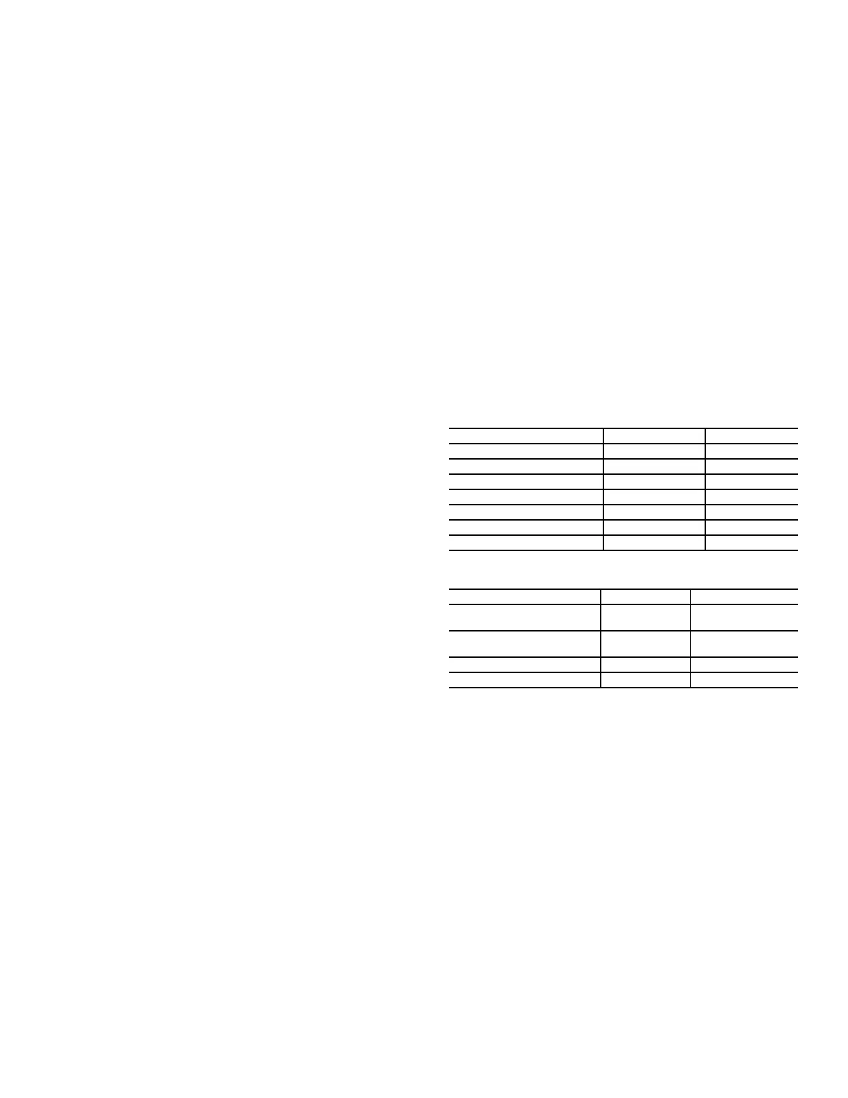
configuration which defines that switches normal state. Table 6
shows the configurable functions and what their normal and
active states are. Table 7 shows the configurable analog input
functions. The switch configurations can be found in the SET-
TINGS UNIT CONFIGURATIONS SWITCH INPUT
CONFIGS sub-menu. The analog input configurations can be
found in the SETTING UNIT CONFIGURATIONS
SWITCH INPUT CONFIGS sub-menu. The configurable in-
put assignment can be viewed in the SERVICE HARD-
WARE ASSIGNED INPUTS/OUTPUTS sub-menu.
GENERAL OPERATION
48/50LC units can provide cooling, dehumidification, heating,
and ventilation. The operating mode (MODE) shows the high-
est level of operation of the unit at any given time. The operat-
ing sub-mode (SUB-MODE) shows the detail operation occur-
ring while under a specific mode. Table 8 shows the MODE
and SUB-MODE values.
Each unit will operate under one of three basic types of control,
thermostat, space temperature sensor, or return air temperature
sensor. There are many inputs, configurations, safety factors,
and conditions that ultimately control the unit. Refer to the spe-
cific operation sections for detail on a specific unit operation.
The control will set the demand based on these types of control
and conditions, which then drives the operating mode.
When thermostat control is enabled (UNIT CONTROL
TYPE), the unit will operate based on discrete input commands
(G, Y1, Y2, Y3, W1, and W2) and there is a one minute time
delay between modes and when re-entering a mode. The G
command calls for ventilation, the Y1, Y2, and Y3 commands
call for cooling, and the W1 and W2 commands call for heat-
ing. Thermostat Control Type (THERMOSTAT TYPE) affects
how cooling operates based on Y1, Y2, and Y3 commands and
if cooling/heating stage time guards are applied.
Table 6 — Configurable Switch Input Functions
FUNCTION DESCRIPTION NORMAL STATE ACTIVE STATE
Humidistat OFF ON
Condensate Overflow LOW HIGH
Filter Status Switch CLEAN DIRTY
Remote Occupancy UNOCC OCCUPIED
Remote Shutdown RUN SHUTDOWN
General Status Switch GOOD ALARM
Enthalpy Switch Input LOW HIGH
Table 7 — Configurable Analog Input Functions
FUNCTION DESCRIPTION SENSOR TYPE SENSOR VALUES
Space Air Relative
Humidity Sensor
0 to 20mA %RH
Return Air Relative
Humidity Sensor
0 to 20mA %RH
Indoor Air CO
2
Sensor 0 to 20mA PPM
Outside Air CO
2
Sensor 0 to 20mA CFM

 Loading...


