8
Internal Wiring
Check all electrical connections in unit control boxes; tighten
as required.
Evaporator Fan
The evaporator fan should be checked and may need to be ad-
justed or specific applications. The unit will have a belt drive
motor powered by a Variable Frequency Drive (VFD). Refer to
the unit product data for fan performance tables and physical
data.
The fan belt and variable pulleys are factory installed and set,
but may need to be adjusted for specific applications. Check
the fan to ensure its rotation is in the proper direction before
adjusting performance. To alter fan performance, first adjust
the pulley settings to provide the application’s full load design
air flow when running at the IDF Maximum Fan Speed (MAX-
IMUM IDF SPEED). The unit operating speeds can then be
adjusted with Free Cooling IDF Speed (FREE COOL IDF
SPEED), High Cooling IDF Speed (HIGH COOL IDF
SPEED), Medium Cooling IDF Speed (MED COOL IDF
SPEED), Low Cooling IDF Speed (LOW COOL IDF
SPEED), Heating IDF Speed (HEATING IDF SPEED), and
Ventilation Only IDF Speed (VENT IDF SPEED). Set the in-
door fan pulley to the greater application design point CFM for
heating or cooling and equal to 100% fan speed. Adjust the
Heating Fan Speed and High Cooling Fan Speed so that the
CFM is not lower than the minimum CFM allowed in the prod-
uct data. If the exact CFM cannot be set by the half turn pulley
settings then adjust the IDF Maximum Fan Speed
(MAXIMUM IDF SPEED) to fine tune the CFM to the appli-
cation requirements. The VFD’s settings should not be used for
adjusting fan performance. Specific VFD information can be
found in the major components section.
Condenser Fans and Motors
Condenser fans and motors are factory set.
Return-Air Filters
Check that correct filters are installed in filter tracks (see phys-
ical data table in unit product data). Do not operate unit with-
out return-air filters. Determine the filter change run time
(DIRTY FILTER TIME) to be set in the quick setup configu-
rations menu.
Outdoor-Air Inlet Screens
Outdoor-air inlet screens must be in place before operating
unit.
Accessory Installation
Check to make sure that all accessories including space ther-
mostats and sensors have been installed and wired as required
by the instructions and unit wiring diagrams.
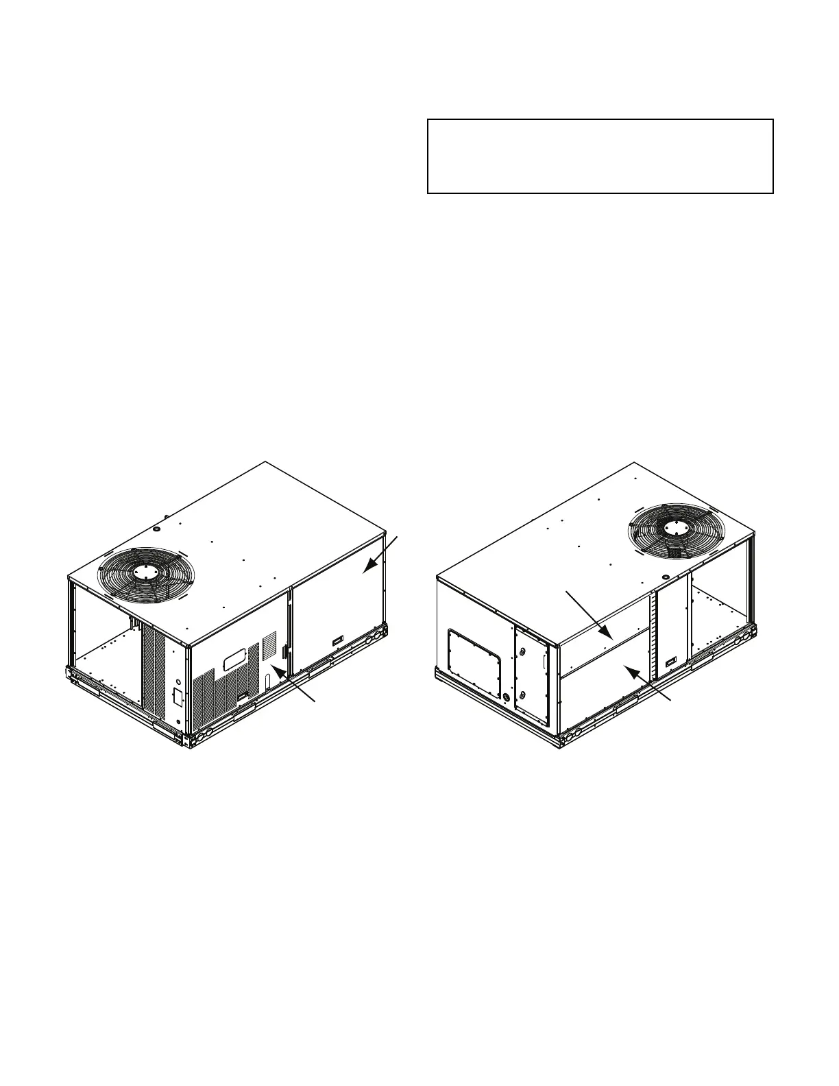
Fig. 6 — 48/50LC Size 04-06 Units – Panel and Filter Locations (48LC*04 Unit Shown)
IMPORTANT: The IDF Maximum Fan Speed (MAXI-
MUM IDF SPEED) RPM must not produce a supply CFM
that is lower than the minimum CFM allowed in the prod-
uct data for heating and cooling.
INDOOR
BLOWER
ACCESS
PANEL
CONTROL BOX
AND GAS SECTION
ACCESS PANEL
INDOOR COIL
ACCESS PANEL
FILTER
ACCESS PANEL
UNIT BACKUNIT FRONT

 Loading...


