18
and a Linkage write. The CCN point OCCUPIED is forced via
an external device such as a ComfortID™ controller or a service
tool: when OCCUPIED is forced to YES, the unit is considered
occupied, when OCCUPIED is forced to NO, the unit is consid-
ered unoccupied. If the unit is being controlled by Linkage, the
occupancy is communicated and mapped to OCCUPIED as an
input. Linkage does not force the point, only write to it, therefore
a force applied to OCCUPIED will override it.
If OCCUPIED is not being forced or written to, proceed to the
level 2 priority.
LEVEL 2 PRIORITY
Level 2 is considered occupant interaction, and consists of
Timed Override and Remote Occupancy Switch. A timed over-
ride button press will override a remote occupancy switch if
both are installed for operation.
While using the programmed schedule, occupancy can be tempo-
rarily switched from unoccupied to occupied by pressing the over-
ride button for approximately 3 seconds on the T-55, T-56, or T-59
space temperature sensor. The length of the override period when
pressing the override button is determined by the Override Time
Limit (TIMED OVR LENGTH). The hours remaining in override
is displayed as Timed Override Hours (TIMED OVR HOURS).
This point can also be changed from the local display or network
to set or change the override period length.
Remote Occupancy Switch (REMOTE OCC SWITCH) can be
forced or configured for operation based on an actual switch.
The physical switch should be configured to either Normally
Open or Normally Closed when the user would like to control
the occupancy with an external switch. This switch is field-
supplied (24v, single pole, single throw [SPST]). There are two
possible configurations for the remote occupancy switch:
1. (REMOTE OCC TYPE = 0) Normally Open Switch
2. (REMOTE OCC TYPE = 1) Normally Closed Switch
If the switch is configured to No Switch (REMOTE OCC
CHAN = None), the switch input value will be ignored and soft-
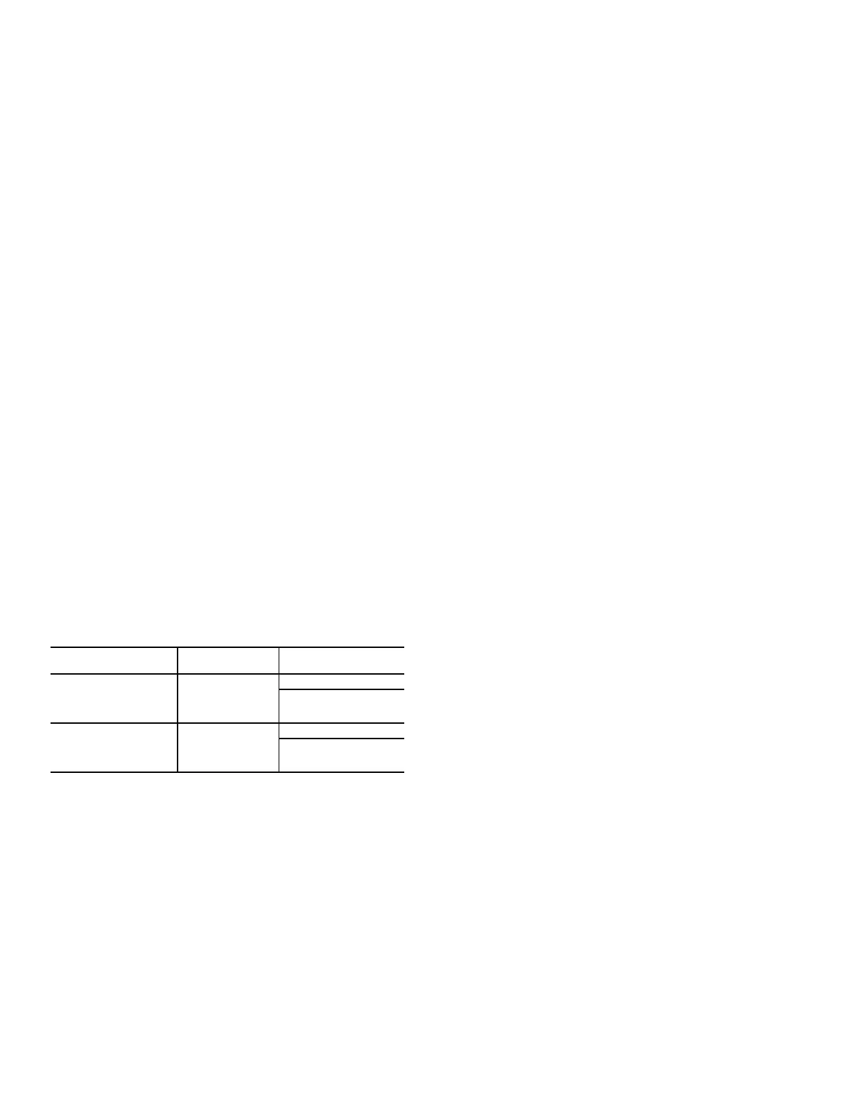
ware will proceed to level 3 priority. For each type of switch, the
appropriate configuration and states are listed in Table 12.
LEVEL 3 PRIORITY
The following occupancy options are determined by the state of
Occupancy Schedule Number (SCHEDULE NUMBER) and
the Global Schedule Broadcast (BROADCAST SCHEDL?).
1. (SCHEDULE NUMBER = 0) The unit is always consid-
ered occupied and the programmed schedule is ignored.
This is the factory default.
2. (SCHEDULE NUMBER = 1-64) Follow the local pro-
grammed schedule. Schedules 1 to 64 are local within the
controller. The unit can only store one local schedule and
therefore changing this number only changes the title of
the schedule table.
3. (SCHEDULE NUMBER = 65-99) Follow the global pro-
grammed schedule. If the unit is configured as a Global
Schedule Broadcaster (BROADCAST SCHEDL? = YES),
the unit will follow the unit’s programmed schedule and
broadcast the schedule so that other devices programmed
to follow this schedule number can receive the schedule. If
the unit is not programmed as a Global Schedule Broad-
caster (BROADCAST SCHEDL? = NO), the unit will
receive broadcasted schedules from a unit programmed to
broadcast this schedule number.
HUMIDITY DEMAND
When the unit is configured for either a Humidistat input
(HUMSTAT CHANNEL) or Space Humidity Sensor (SPRH
SENS CHANNEL), the level 5 demand in Table 9 will include
a determination of dehumidification demand.
HUMIDISTAT
When receiving an active input from the Humidistat (HUMID-
ISTAT), dehumidification will be demanded.
SPACE RELATIVE HUMIDITY
On units with a relative humidity sensor, when the received value
of space relative humidity (SPRH LEVEL) has exceeded the hu-
midity set point (SPRH SET POINT), dehumidification will be
demanded. This demand will remain until the space relative hu-
midity has fallen below the humidity set point by more than the
humidity set point deadband (SPRH DEADBAND). This would
come from the space humidity sensor or building network.
Indoor Fan Operation
These units use the Staged Air Volume (SAV™) method of
controlling the supply fan for a typical constant volume rooftop
unit. This control method employs a variable frequency drive
(VFD) to operate the supply fan at different speeds in order to
achieve energy savings through reduced fan power. This meth-
od is specifically not concerned with controlling static pressure
in the supply duct, but rather with setting different fan speeds
for different operating conditions, such as ventilation mode or
part-load mechanical cooling.
The SAV function is NOT a Variable Air Volume (VAV) func-
tion. The fan adapts its speed to one of eight options based on
mode and current state to satisfy a demand. The eight speeds
consist of: off (0%) and seven configurable values. The seven
configurable fan speeds are: Maximum Speed (MAXIMUM
IDF SPEED), Ventilation (VENT IDF SPEED), Heating
(HEATING IDF SPD), Free Cool (FREE COOL IDF SPD),
Mechanical Low Cooling (LOW COOL IDF SPD), Mechanical
Medium Cooling (MED COOL IDF SPD), and Mechanical
High Cooling (HIGH COOL IDF SPD), The VFD is powered
direct from the distribution block or circuit breaker (CB) and is
always on with power applied unless the CB is tripped. When
the thermostat or space sensor control conditions require the fan
on, the VFD will then ramp to desired speed. Fan speed is al-
ways calculated by evaluating the current applicable conditions.
Each fan speed condition is evaluated independently, and the
highest fan speed is used. For example, if a cooling call occurs
during Ventilation mode, the unit mode will transition to cooling
but the fan speed is set to the higher of the two (VENT IDF
SPEED or LOW COOL IDF SPD). Refer to the speed configu-
rations below for when the fan will run at the various speeds.
DIRECT DRIVE UNITS
Alternately, 48/50LC*04-06 units can have either a direct drive
Electronic Commutated Motor (ECM) fan system or a belt drive
motor powered by a Variable Frequency Drive (VFD). An IDF-
TYPE=1 indicates a unit with VFD, while an IDFTYPE=2 indi-
cates a direct drive system. Refer to the unit product data for fan
performance tables and physical data. On direct drive units, the
ECM has 5 speed taps to allow a range of fan performance. The
control has 3 output wires to connect to 3 different taps. At the
factory, the low and high speed wires are connected to the first
and second speed taps, respectively. The ventilation speed tap is
disconnected. The speed taps increase in speed the higher the tap
number, so tap 1 is the lowest speed and tap 5 is the highest
speed. If the low and high speed wires are moved to higher taps,
the ventilation speed wire can be wired into the motor. To
Table 12 — Switch Configurations
TYPE OF SWITCH
SWITCH
CONFIGURATION
STATE OF SWITCH
AND OF OCCUPANCY
Occupied when closed
or
Unoccupied when
open
Normal Open (0)
Open and Unoccupied
Closed and Occupied
Occupied when open
or
Unoccupied when
closed
Normal Closed (1)
Open and Occupied
Closed and Unoccupied

 Loading...


