40
Control Module Communication
RED LED
Proper operation of the MBB control board can be visually
checked by looking at the red status LED. When operating cor-
rectly, the red status LED should blink at a rate of once every
2 seconds. If the red LED is not blinking, verify that correct
power is being supplied. A blinking red LED at the rate of once
per second means that software is not loaded on the board. Al-
so, be sure that the board is supplied with the current software.
If necessary, reload current software. A board LED that is lit
continuously should be replaced.
GREEN LED
The MBB has one green LED. The Local Equipment Network
(LEN) LED should always be blinking whenever power is on.
If LEN LED is not blinking, check LEN connections for poten-
tial communication errors (MBB J15, J16, J17, and on the Dis-
play J2). Communication between modules is accomplished by
a 3-wire sensor bus. These 3 wires run in parallel from module
to module. The MBB J17 and Display J2 connectors provide
both power and communication directly at the connector for
accessories like the Navigator™ display. The MBB J15 con-
nector provides a LEN interface to the indoor fan VFD.
YELLOW LED
The MBB has one yellow LED which is used to indicate Build-
ing Automated System (BAS) communication activity. The
LED will blink when the MBB transmits a message on the bus.
Communication Failures
If the Indoor Fan VFD or Navigator display Communication
Failure or the green or yellow LED’s do not flash on the boards,
then the problem could be the communication chip on one of the
control boards (MBB). Use an ohm meter to measure the resis-
tance on the communication pins of the boards to determine if
the board is bad. If the reading is less then half the value indicat-
ed in Table 17, then the board needs to be replaced.
Cooling Troubleshooting
Use the SystemVu™ Display or a CCN device to view the
cooling status display and the cooling diagnostic display (see
Appendices) for information on the cooling operation. Check
the current alarms and alarm history for any cooling alarm
codes and correct any causes. (See Table 16.) Verify any
unique control configurations per installed site requirements or
accessories.
If alarms conditions are corrected and cleared, operation of the
compressors and fans may be verified by using the Service Test
mode. (See Table 4.) See Table 18 for general cooling service
analysis.
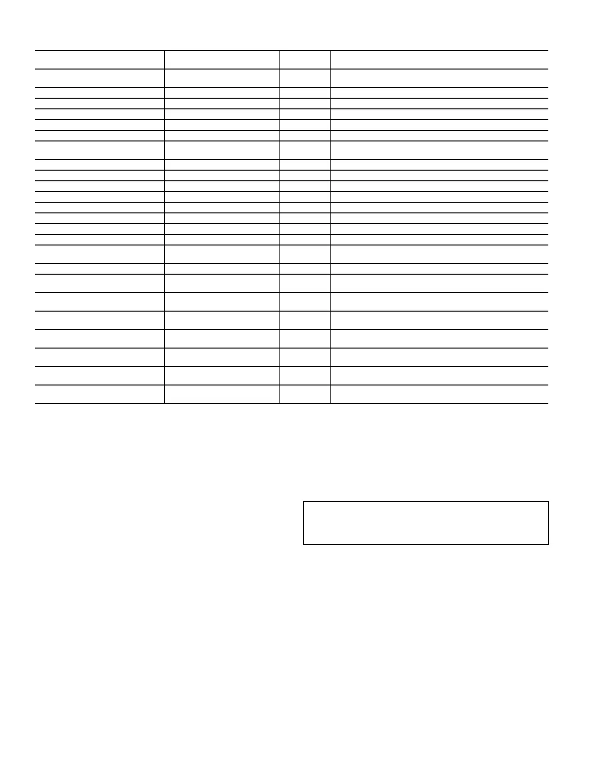
A606-IDF VFD VOLTAGE
WARNING
IDF speed reduced Automatic Motor improper size, motor overload, or configuration errors.
A607-IDF VFD CURRENT LIMIT IDF speed reduced Automatic Motor improper size, motor overload, or configuration errors.
A608-IDF VFD WARNING IDF speed reduced Automatic Motor improper size, motor overload, or configuration errors.
F611-IDF VFD EARTH FAULT Unit Shutdown Automatic VFD fault, refer to VFD section
F612-IDF VFD CTL WORD LOSS Unit Shutdown Automatic VFD fault, refer to VFD section
F613-IDF VFD OVER CURRENT Unit Shutdown Automatic VFD fault, refer to VFD section
F614-IDF VFDMOTOR OVER
TEMP
Unit Shutdown Automatic VFD fault, refer to VFD section
F615-IDF VFD OVERLOAD Unit Shutdown Automatic VFD fault, refer to VFD section
F616-IDF VFD UNDER VOLTAGE Unit Shutdown Automatic VFD fault, refer to VFD section
F617-IDF VFD OVER VOLTAGE Unit Shutdown Automatic VFD fault, refer to VFD section
F618-IDF VFD SHORT CIRCUIT Unit Shutdown Automatic VFD fault, refer to VFD section
F619-IDF VFD MAIN PHASE LOSS Unit Shutdown Automatic VFD fault, refer to VFD section
F620-IDF VFD PHASE U LOSS Unit Shutdown Automatic VFD fault, refer to VFD section
F621-IDF VFD PHASE V LOSS Unit Shutdown Automatic VFD fault, refer to VFD section
F622-IDF VFD PHASE W LOSS Unit Shutdown Automatic VFD fault, refer to VFD section
F623-IDF VFD CONTROL
VOLTAGE
Unit Shutdown Automatic VFD fault, refer to VFD section
F624-IDF VFD SUPPLY VDD Unit Shutdown Automatic VFD fault, refer to VFD section
A700-ECON NOT MODULATING Alert Generated Automatic
No economizer motion. Check damper blades, gears, and
actuator. Actuator direction control switch (CCW, CW) wrong.
A701-ECON STUCK CLOSED Alert Generated Automatic
No economizer motion. Check damper blades, gears, and
actuator. Actuator direction control switch (CCW, CW) wrong.
A702-ECON STUCK OPEN Alert Generated Automatic
No economizer motion. Check damper blades, gears, and
actuator. Actuator direction control switch (CCW, CW) wrong.
A703-ECON MECH
DISCONNECTED
Alert Generated Manual
No economizer motion. Check damper blades, gears, and
actuator. Actuator direction control switch (CCW, CW) wrong.
A710-ECON NOT COOLING Alert Generated Automatic
No economizer motion. Check damper blades, gears, and
actuator. Actuator direction control switch (CCW, CW) wrong.
A711-ECON IMPROPER COOLING Alert Generated Automatic
No economizer motion. Check damper blades, gears, and
actuator. Actuator direction control switch (CCW, CW) wrong.
A712-EXCESSIVE OUTDOOR AIR Alert Generated Automatic
No economizer motion. Check damper blades, gears, and
actuator. Actuator direction control switch (CCW, CW) wrong.
Table 16 — SystemVu™ Controller Alarm Codes (cont)
FAULT OR ALERT
ACTION TAKEN
BY CONTROL
RESET
METHOD
PROBABLE CAUSE
IMPORTANT: The resistive values should be read when
the board is powered off, the unit is locked out, and board
connectors are disconnected.

 Loading...


