37
To reduce waste, the refrigerant and the oil must be
transferred in accordance with applicable regulations,
using methods that limit refrigerant leaks and pressure
drops and with materials that are suitable for the products.
Any leak detected must be repaired immediately.
The compressor oil that is recovered during maintenance
contains refrigerant and must be treated accordingly.
The refrigerant under pressure must not be vented to
atmosphere.
If a refrigerant circuit is opened, plug all openings if the
operation takes up to one day, or charge the circuit with
oxygen free nitrogen.
11.4 - Tightening torques for the main electrical
connections
11.4.1 - Tightening torques for the main electrical
connections
Component Designation in the
unit
Value
(Nm)
Customer connections
M10 screw-nut on phases L1 /L2 /L3 30
Nut on ground terminals (M12) PE 70
Compressor connections in the control box
M10 screw-nut on disconnect switch
downstream bars
30
M8 hexagon socket head cap 15-20
M10 hexagon socket head cap 25-30
Nut on ground terminal (M10) 5
Circuit breaker terminal screw 3RV2*1* QF_ /QM_ 0.8-1.2
Circuit breaker terminal screw 3RV2*2* QF_ /QM_ 2.0-2.5
Connections in fan controllers
Screw in power supply terminals (line) 1.8
Screw in motor terminals 1.8
Ground screw 3
Connections on compressor
M12 nuts on phases 25
M12 screw on ground EC_ 25
Compressor variable speed drive
6 M10 nuts R/S/T U/V/W 19
2 M10 or M8 nuts GND 19
9 M8 nuts (with fuses and busbars) see picture 9.6
ATTENTION: The tightening of the connections at the
compressor terminals requires special precautions. Please
refer to the chapter below.
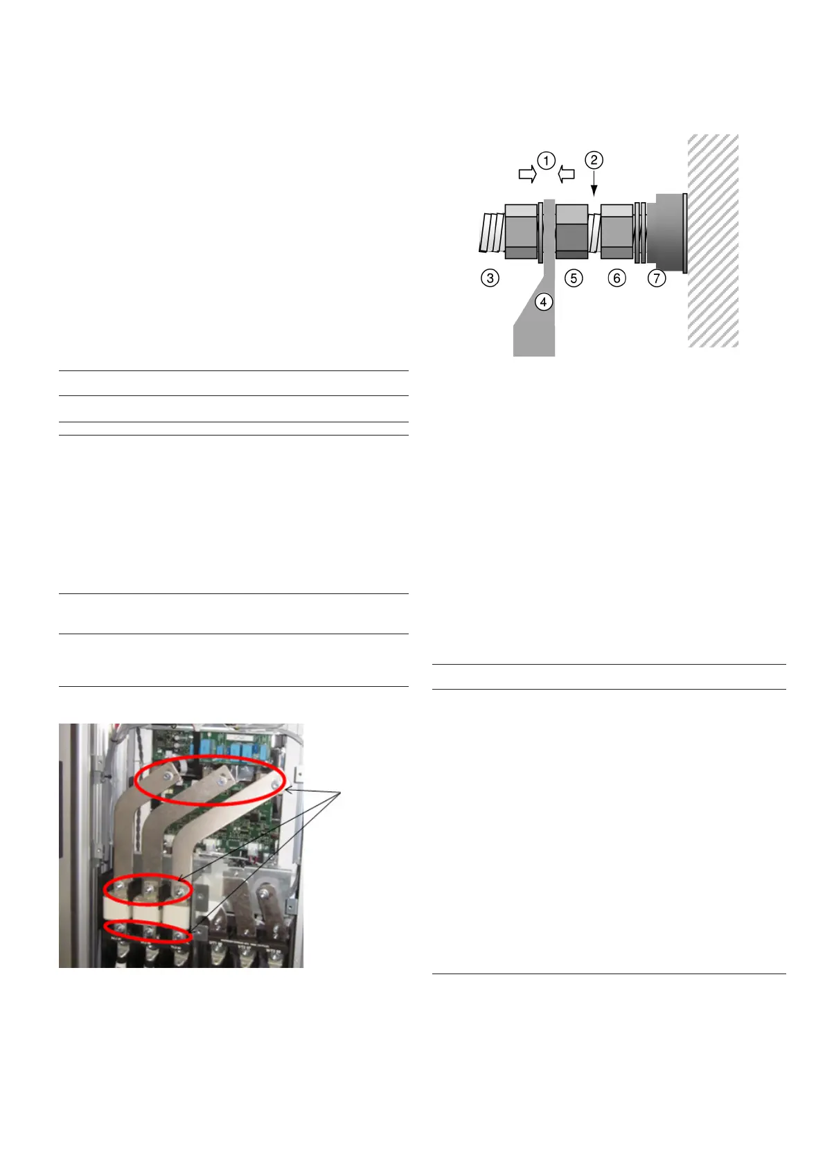
11.4.2 - Connection precautions for the compressor power
terminals
These precautions must be applied during an intervention
that requires the removal of the power conductors connected
to the compressor supply terminals.
1. Application torque for tightening the clamp
2. Avoid contact between clamping nuts
3. Clamping nut husk
4. Pod at
5. Against nut
6. Clamping nut terminal
7. Insulator
The tightening nut of terminal (6) supporting the isolator (7)
must never be loosened, as ist ensures terminal tightness
and compressor leak tightness.
When securing the cable lug (4), apply the required torque
between the clamping nut (3) and the backing nut (5). During
this procedure a counter-torque must be applied to the
backing nut (5). The backing nut (5) must not be in contact
with the terminal securing nut (6).
11.5 - Tightening torques for the main bolts and screws
Screw Type Utilisation Value
(Nm)
Tapping screws
D = 4.8
Condensing module, housing, supports 4.2
H M8 screw Condensing module, fan blade 18
M10 Taptite Condensing module, frame, structure, control box
xing, compressor xing, oil separators xing
30
M6 Taptite Mounting pipes, enclosure 7
M8 H screw MCHE coil nut + studs 14
M6 H screw Piping collar 10
M10 H screw Oil separator xing 7
M10 H screw Compressor xing (Nylstop nut) 23
M8 H screw Filter drier cover 35
M12 H screw Economiser port ange 40
M16 H screw Oil separator ange nut +stud (TS/TT/TU) 190
M16 H screw Suction ange TS/TT with gasket 190
M16 H screw Heat exchanger water boxes 190
M20 / M16 H
screw
Suction ange TU / TS O-ring 130
3/8 Nut ORFS Oil line 65
3/8 Nut ORFS Oil line 26
M12/M16 Hex nut Victaulic collar 4'' (M12 nut) and 5'' (M16 nut) on
suction line
65
M16 Hex nut Victaulic collar 6'' (M16 nut) on suction 110
11.6 - Condenser coil
We recommend, that coils are inspected regularly to check
the degree of fouling. This depends on the environment
where the unit is installed, and will be worse in urban and
industrial installations and near trees that shed their leaves.
9 M8 nuts

 Loading...