→ CARE AND MAINTENANCE
For continuing high performance, and to minimize possible equipment failure, it is essential that periodic maintenance be performed on this
equipment. The only required maintenance that may be performed by the consumer is filter maintenance.
WARNING: Disconnect all power to unit before servicing field wires or removing control package. The disconnect
(when used) on access panel does not disconnect power to the line side of disconnect, but does allow safe service to all
other parts of unit. If unit does not have a disconnect, disregard the foregoing. Instead, make sure that a disconnecting
means is within sight from, and is readily accessible from, the unit. Disconnect all electrical power to unit before performing
any maintenance or service on it. A failure to follow this warning can cause electrical shock, fire, personal injury, or death.
The minimum maintenance requirements for this equipment are as follows:
1. Inspect and clean or replace air filter each month or as required.
2. Inspect cooling coil, drain pan, and condensate drain each cooling season for cleanliness. Clean as necessary. An inspection port is provided
on all A-coil delta plates. Remove plastic plug to inspect.
3. Inspect blower motor and wheel for cleanliness each heating and cooling season. Clean as necessary.
4. Inspect electrical connections for tightness and controls for proper operation each heating and cooling season. Service as necessary.
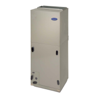
Fig. 18—PCB Mounted with Wiring and Accessory Air
Cleaner Relay
A95277
EASY SELECT
D
H
R
W
1
W
2
Y
1
Y/ Y
2
G
O
C
HEATER/MOTOR
CEBD430226-01B CESS430226-01B
AUX HEAT KW/CFM
0-30
1075
SEC1 SEC2
J1
J2
AC/HP SIZE
036 030 024 018
AC
HP-COMFORT
HP-EFF
NOM HI
ENH
LO
SYSTEM TYPE
AC/HP CFM ADJUST
ON/OFF DELAY
CONTINUOUS FAN
MED HI YELLO
AUX1 HUM1
AUX2
24VAC
GRY
HUM2
YEL
WHT
BLK
ORN
BLU
VIO
0-20
875
0-10
725
0
90
30
90
0
0
0-5
625
TM
COM
NO
BLK
BLK
RED
RED
24VAC RELAY
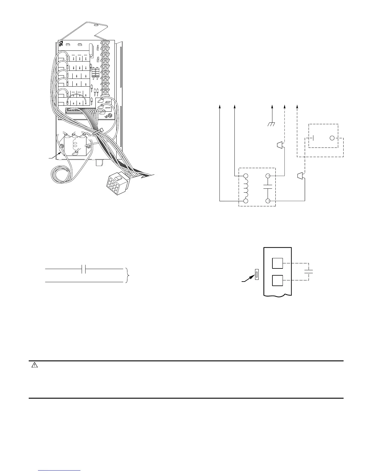
Fig. 19—EAC Relay Wiring Schematic
A95318
24 VAC RELAY
FK4C
230 VAC OR
115 VAC BRANCH CKT
AUX1
(C)
AUX2
(G)
GND HOT NEUT
GRN
BLK
WHT
EAC
PLUG
NO
COM
BLK
BLK
RED
RED
BLK
Fig. 20—Humidifier Wiring
A95317
HUMIDISTAT
TO HUMIDIFIER
HUMIDIFIER WIRING
HUM 1
(C)
HUM 2
(G)
24-VAC
Fig. 21—Humidistat Wiring for De-Humidify Mode
A95316
EASY SELECT
BOARD TERMINAL
BLOCK
D
H
J1
R
HUMIDISTAT
REMOVE
JUMPER
—15—
 Loading...