INSTALLATION
PROCEDURE 1—CHECK EQUIPMENT
Unpack unit and move to final location. Remove carton taking care not to damage unit.
Inspect equipment for damage prior to installation. File claim with shipping company if shipment is damaged or incomplete. Locate unit rating
plate which contains proper installation information. Check rating plate to be sure unit matches job specifications.
PROCEDURE 2—MOUNT FAN COIL
Unit can stand or lie on floor, or hang from ceiling or wall. Allow space for wiring, piping, and servicing unit.
IMPORTANT: When unit is installed over a finished ceiling and/or living area, building codes may require a field-supplied secondary condensate
pan to be installed under the entire unit. Some localities may allow as an alterative the running of a separate, secondary condensate line. Consult
local codes for additional restrictions or precautions.
When installing any fan coil over a finished ceiling and/or living area, installation of a secondary drain pan under entire unit to avoid damage to
ceiling is recommended.
FK4C Fan Coils can be installed for upflow and horizontal-left applications as factory shipped. Units can be installed for horizontal-right
applications with field modifications. Units may be converted for downflow applications using factory-authorized accessory kit.
NOTE: To ensure proper drainage for horizontal installations, unit must be installed so it is within 1/8 in. level of the length and width of unit.
A. Upflow Installation
If return air is to be ducted, install duct flush with floor. Set unit on floor over opening.
Only use return-air opening provided. All return air must pass through the coil. (See Fig. 4.)
B. Modular Units
The FK4C Fan Coil in size 006 is a 2-piece modular unit. Modular construction allows installer to disassemble unit into 2 components, coil box
and blower box, for ease of installation. (See Fig. 5.)
To disassemble unit, remove rear corner brackets by removing 2 screws which secure brackets. (See Fig. 5.) Remove either 2 screws in each front
corner of coil box, or 2 screws in blower box. Do not remove all 4 screws in each corner. (See Fig. 5.) Sections may now be separated by lifting
top section from lower section.
To reassemble, reverse above procedure. Be certain to reinstall all fasteners when reassembling.
C. Horizontal Installations
Be sure installation complies with all applicable building codes that may require installation of a secondary condensate pan.
1. Arrange support for unit by setting it in or above secondary condensate pan.
2. When suspending unit from ceiling, dimples in casing indicate proper location of screws for mounting metal support straps. (See Fig. 6.)
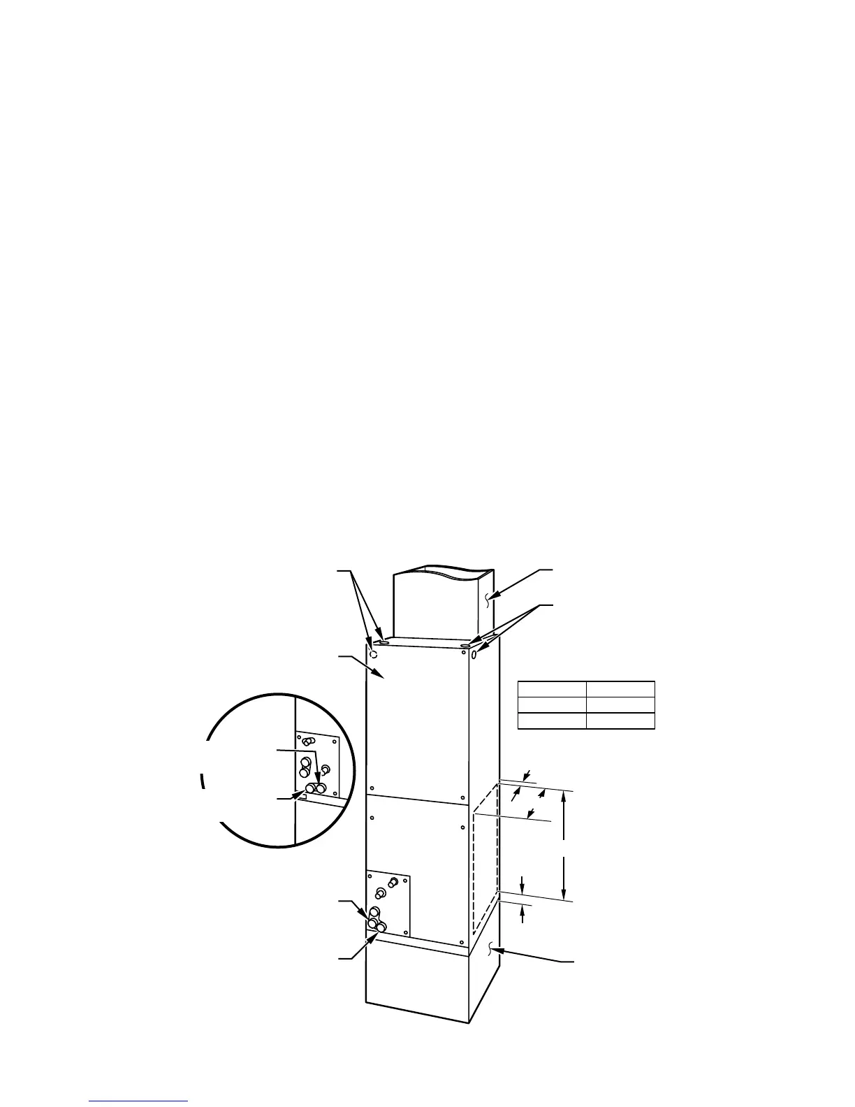
Fig. 4—Slope Coil Unit in Upflow Application
A95621
A COIL
UNITS
POWER ENTRY
OPTIONS
LOW VOLT
ENTRY
OPTIONS
FIELD MODIFIED
SIDE RETURN
LOCATION FOR
SLOPE COIL
UNITS ONLY
FIELD SUPPLIED
RETURN PLENUM
UPFLOW/DOWNFLOW
SECONDARY DRAIN
UPFLOW/DOWNFLOW
PRIMARY DRAIN
UNIT
001
003
A
17 In.
19 In.
A
1
1
⁄
2
″
2
1
⁄
2
″
19″
FIELD SUPPLIED
SUPPLY DUCT
24-IN. FRONT SERVICE
CLEARANCE
UPFLOW/DOWNFLOW
SECONDARY DRAIN
UPFLOW/DOWNFLOW
PRIMARY DRAIN
—4—
 Loading...