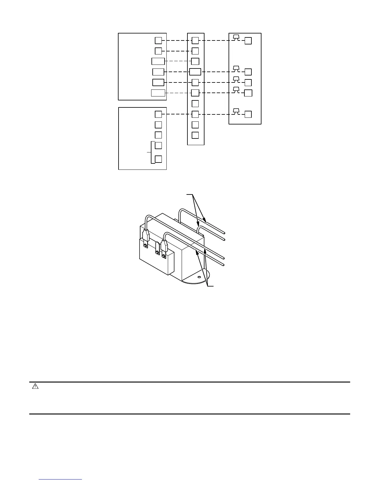
Transformer is factory wired for 230-v operation. For 208-v applications, disconnect black wire from 230-v terminal on transformer and connect
it to 208-v terminal. (See Fig. 12.)
The secondary circuit of transformer is protected by a 5-amp fuse mounted on printed-circuit board.
IMPORTANT: Do not use outdoor thermostat with Intelligent Heat.
D. Ground Connections
Use UL listed conduit and conduit connector to connect supply wire(s) to unit and obtain proper grounding. Grounding may also be accomplished
by using grounding lug provided in control box. Use of dual or multiple supply circuits will require grounding of each circuit to ground lugs
provided on unit and heaters.
WARNING: The cabinet must have an uninterrupted or unbroken ground according to NEC, ANSI/NFPA 70 and local
codes to minimize personal injury if an electrical fault should occur. The ground may consist of electrical wire or metal
conduit when installed in accordance with existing electrical codes. Failure to follow this warning could result in an electrical
shock, fire, or death.
PROCEDURE 5—FK4C FAN COIL SEQUENCE OF OPERATION
The FK4C will supply airflow in a range which is more than twice the range of a standard fan coil. It is designed to provide nominal cooling
capacities at a 50°F evaporator temperature and the required airflow which enables it to match with 4 air conditioner or heat pump system sizes.
Table 1 outlines the CFM range for the different FK4C Fan Coil sizes.
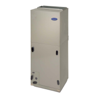
Fig. 11—Single Speed Heat Pump Wiring with Intelligent Heat
A96063
24 VAC HOT
FAN
HEAT STAGE 2
COOL/HEAT
STAGE 1
RVS COOLING
HEAT STAGE 3
R
G
W/W1
Y/Y2
O/W2
Y1/W2
R
G
24 VAC COMM.
RVS HEATING
TROUBLE
OUTDOOR
SENSOR
CONNECTION
C
B
L
S1
S2
C
Y
C
R
O
W2
MODEL 2S
THERMOSTAT
FK4
FAN COIL
SINGLE-SPEED
W1
Y/Y2
O
W2
L
E
Y1
Fig. 12—Transformer Connections
A94067
230
C
208
BRN
RED
YEL
BLK
SECONDARY
PRIMARY
—9—
→
 Loading...