All units are shipped with power plug and stripped leads for connection of field wiring to units without electric heat.
1. Connect 208/230v power leads from field disconnect to yellow and black-striped leads.
2. Connect ground wire to unit ground lug.
3. If unit contains accessory electric heater, remove and discard power plug from fan coil and connect male plug from heater to female plug
from unit wiring harness. (See Electric Heater Installation Instructions.)
B. 24-V Control System Connections to Unit Printed-Circuit Board (PCB)
Refer to unit wiring instructions for recommended wiring procedures. Use No. 18 AWG color-coded, insulated (35°C minimum) wires to make
low-voltage connections between thermostat and unit. If thermostat is located more than 100 ft from unit (as measured along the low-voltage
wires), use No. 16 AWG color-coded, insulated (35°C minimum) wires. PCB is circuited for single-stage heater operation. When additional heater
staging is desired using 2-stage or outdoor thermostats, see applicable outdoor unit instructions. Remove Jumper J2 on PCB.
1. The 5-, 8-, and 10-kw heaters are single stage only.
2. The 15- and 20-kw heaters are adaptable for 2-stage operation.
3. The 24- and 30-kw heaters are adaptable for up to 3-stage operation.
Connect low-voltage leads to thermostat and outdoor unit. (See Fig. 9 and 10.)
C. Intelligent Heat Option
Intelligent Heat staging of the electric heat package is possible when the FK4C is installed as a part of a single-speed heat pump system using a
corporate 2-speed programmable thermostat (model TSTATXXP2S01-A) and any 1 of the following electric heat packages:
KFAEH2501N09, KFAEH2601F15, KFAEH2801C15, KFAEH2701S15, KFAEH1001F24 or KFAEH1101F30.
To activate Intelligent Heat:
1. Set thermostat dip switch C to off and D to on.
2. On the fan coil Easy Select board, remove Jumper J2 (W1-W2).
3. Complete system low-voltage wiring as shown in Fig. 11.
NOTE: Where local codes require thermostat wiring be routed through conduit or raceways, splices can be made inside the fan coil unit. All
wiring must be NEC Class l and must be separated from incoming power leads.
A factory-authorized disconnect kit is available for installation of 0- through 10-kw applications. When electric heat packages with circuit breakers
are installed, the circuit breaker can be used as a disconnect.
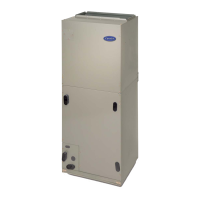
Fig. 9—Single-Speed Heat Pump Wiring
A95313
Thermostat
Subbase
FK4C
Terminal
Block
Outdoor
Terminal
Board
CCC
W
1
W
2
W
2
L
GG
G
O
/W
2
OO
RRR
Y
Y
/
Y2
Y
/
Y2
W
/
W1
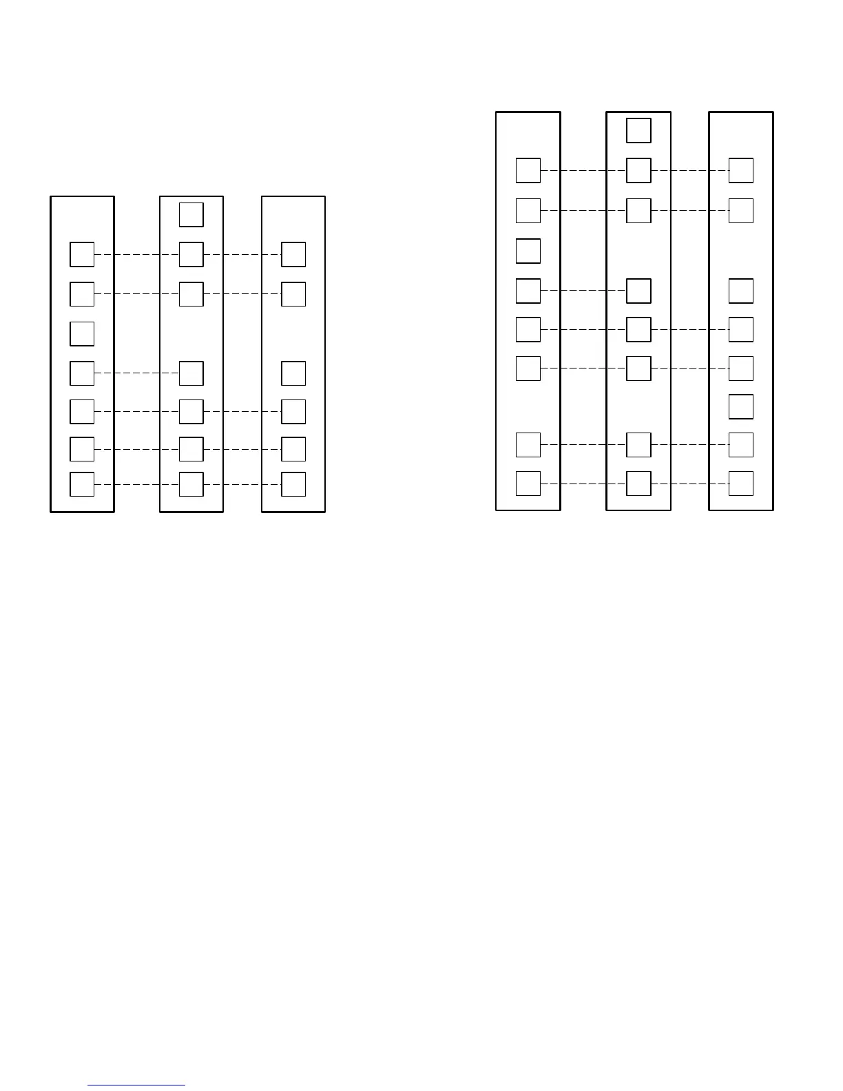
Fig. 10—Two-Speed Heat Pump Wiring
A95314
Thermostat
Subbase
FK4C
Terminal
Block
Outdoor
Terminal
Board
CCC
W
1
W
2
W
2
L
GGG
OO
RRR
Y
/
Y2
Y
2
E
Y
1
Y
1
O
/W
2
Y
/
Y2
Y
1
/
W
2
W
/
W1
—8—
→
→
 Loading...