7
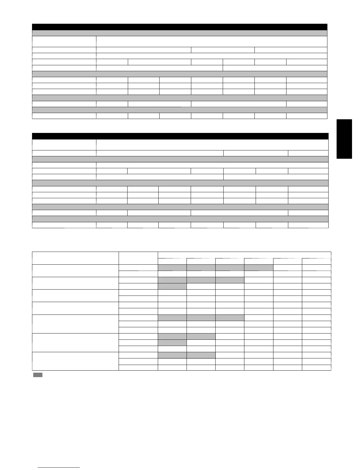
SPECIFICATIONS
MODEL FY4A 018 024 030 036 042 048 060
COIL
Puronr Refrigerant
Metering Device
T X V --- f a c t o r y i n s t a l l e d h a r d --- s h u t o f f , b i --- f l o w t y p e f o r h e a t pu m p a p p l i c a t i o n
TXV Size 2ton 3ton 4ton
Rows/Fins Per In. 3 / 14.5
Face Area (Sq. Ft.) 2.23 2.97 3.46 4.45 5.93 7.42
Configuration Slope A
FAN
CFM (Nominal) 600 800 1000 1200 1400 1600 2000
Motor Type PSC PSC PSC PSC PSC PSC PSC
Motor Hp 1/6 1/4 1/4 1/3 1/2 3/4 3/4
FILTER*
21--- 1/2” / 546 mm X 13” / 330 mm 16 ---3/8” / 417 mm 19--- 7/8” / 505 mm 23--- 5/16” / 585 mm
CABINET CONFIGURATION OPTIONS
1 --- p i e c e 1 --- p i e c e 1 --- p i e c e 1 --- p i e c e 1 --- p i e c e 1 --- p i e c e Modular
*Filter must be field ---supplied for FY4A units.
MODEL FA4C 018 024 030 036 042 048 060
R --- 2 2 R e f r i g e r a n t
Metering Device
T X V --- f a c t o r y i n s t a l l e d h a r d --- s h u t o f f , b i --- f l o w t y p e f o r h e a t p u m p a p p l i c a t i o n
TXV SIZE 3ton 5ton 6ton
COIL
Rows/Fins Per In. 3 / 14.5
Face Area (Sq. Ft.) 2.23 2.97 3.46 4.45 5.93 7.42
Configuration Slope A
FAN
CFM (Nominal) 600 800 1000 1200 1400 1600 2000
Motor Type PSC PSC PSC PSC PSC PSC PSC
Motor Hp 1/6 1/4 1/4 1/3 1/2 3/4 3/4
FILTER*
21--- 1/2” / 546 mm X 13” / 330 mm 16--- 3/8” / 417 mm 19--- 7/8” / 505 mm 23--- 5/16” / 585 mm
CABINET CONFIGURATION OPTIONS
1 --- p i e c e 1 --- p i e c e 1 --- p i e c e 1 --- p i e c e 1 --- p i e c e 1 --- p i e c e Modular
*Filter must be field ---supplied for FA4C units.
PERFORMANCE DATA
AIRFLOW PERFORMANCE (CFM)
MODEL & SIZE
BLOWER
SPEED
TOTALEXTERNALSTATICPRESSURE
0.10 0.20 0.30 0.40 0.50 0.60
FY4A , FA4C
018
High 816 795 753 690 607 504
Low 633 620 588 538 468 380
FY4A , FA4C
024
High 1055 991 926 860 793 724
Low 934 878 818 754 686 614
FY4A , FA4C
030
High 1070 1032 978 908 822 721
Low 910 888 849 791 715 621
FY4A , FA4C
036
High 1352 1316 1273 1223 1167 1103
Low 1137 1112 1081 1043 998 946
FY4A , FA4C
042
High 1720 1668 1602 1521 1426 1316
Medium 1576 1540 1488 1421 1338 1239
Low 1388 1367 1330 1278 1209 1124
FY4A , FA4C
048
High 1902 1824 1743 1659 1571 1479
Medium 1830 1763 1690 1611 1527 1436
Low 1625 1584 1531 1465 1387 1296
FY4A , FA4C
060
High 2128 2050 1965 1875 1778 1674
Medium 1959 1898 1829 1750 1663 1566
Low 1748 1709 1659 1598 1525 1442
--- S h a d i n g --- Ai r f l o w o u t s i d e 4 5 0 c f m / t o n .
NOTES:
1. Airflow based upon dry coil at 230v with fa ctory ---approved f ilter and electric hea ter (2 element h ea ter sizes 18 thru 36, 3 element heater sizes 42 thru 60).
Airflow at 208 volts is approximately 10% l o wer.
2. To avoid potential for condensate blowing out of drain pan prior to making drain trap:
Return static pressure must be less than 0.40 in. wc.
Horizontal applications of 042 --- 060 sizes must h ave supply static greater than 0.20 in. wc.
3. Airflow above 400 cfm/ton on 048--- 060 size could result in condensate blowing off coil or splashing out of drain pan.
FY4A / FA4C

 Loading...