INSTALLATION
4
6095756-R2 EN
3
C3
C4
C2
C1
4
3
5
4
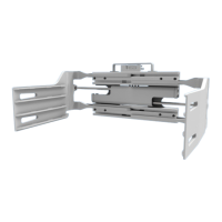
Mark the mounting location on the truck cowl.
Grind and clean the area in preparation for
welding. Tack-weld the subplate to the cowl
and mount the valve to the subplate with the
capscrews supplied in the kit.
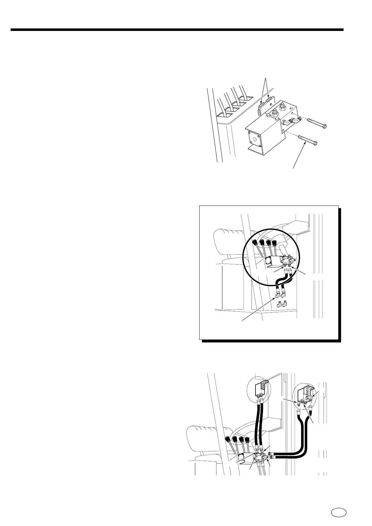
Rotate Function – Measure and assemble two
hoses (user-supplied) to run from the control valve
C1 and C4 ports to the RH hose reel. Install
hoses.
Swing Function – Measure and assemble two
hoses (user-supplied) to run from the control valve
C2 and C3 ports to the LH 4-port hose reel 3 and
4 ports. Install hoses.
Measure and assembly two hoses (user-supplied)
to run from the solenoid valve P and T ports to the
truck valve ports. Install the hoses.
IMPORTANT: Proceed to step 7 if lift truck is
equipped with mast internal hose reeving.
Swing Control Valve Installation
NOTE: Horizontal
mount only shown
Tack-weld subplate
to truck cowl
8mm x 90mm long
capscrews
RC0728.eps
Truck Auxiliary
Valve Ports
Port T
Port P
Installation with RH 2-Port and LH 4-Port
Hose Reels
RH 2-port
Hose Reel
LH 4-Port
Hose Reel
ROTATE
Function
Ports 1 and 2
for CLAMP/
OPEN circuit
only
SWING
Function
 Loading...