INSTALLATION
3
6095756-R2 EN
Swing Control Valve Installation
Follow the steps shown to install a Swing Frame Paper Roll
Clamp. Read and understand all WARNING statements.
If you don't understand a procedure, ask your supervisor
or call the nearest Cascade Service Department for
assistance.
NOTE: Swing Frame Clamps require a solenoid-operated
control valve group to convert a two function auxiliary
control valve to three function operation.
For hose reel information, refer to Installation Instructions
673835 for THINLINE
TM
2-Port Hose Reels and Installation
Instructions 675395 for THINELINE
TM
2-Port Hose Reels (for
masts without internal reeving). Control valve groups for
different voltages are listed in the table shown.
1
2
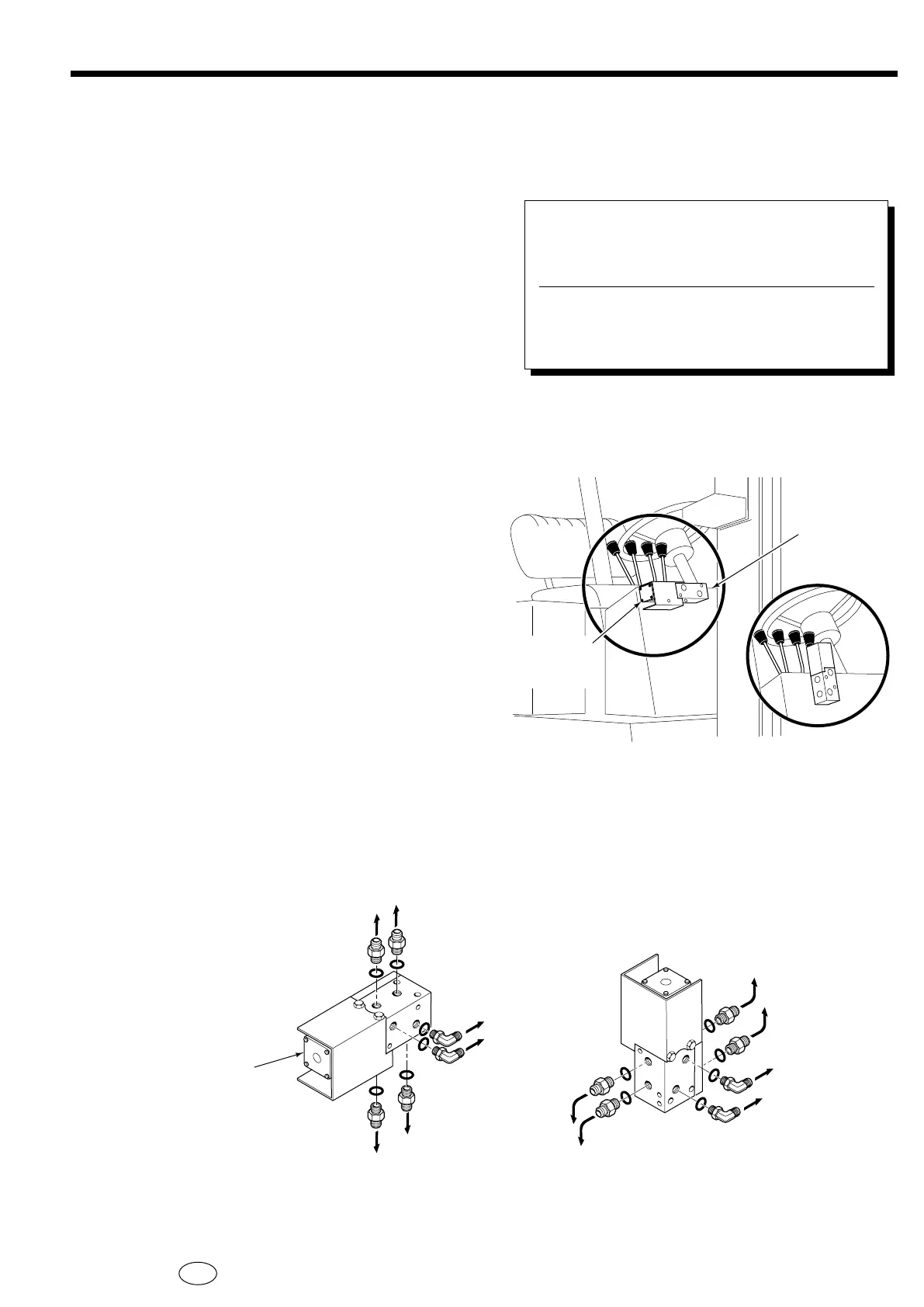
Determine an appropriate mounting location for
the control valve on the truck cowl. The valve can
be mounted horizontally or vertically. The valve
must not extend outside the width of the cowl or
interfere with the truck mast.
Assemble the solenoid valve, fittings, cover and
subplate. Position the assembly on the truck cowl
noting any clearance problems.
Control Valve Group
With Knob
Part Number
With Low
Profile Switch
Part Number Truck Voltage
674924
674925
674926
674927
6014883
6014885
6014886
6014887
12V
24V
36V
48V
RC0725.eps
HORIZONTAL MOUNT
HORIZONTAL MOUNT
VERTICAL MOUNT
VERTICAL MOUNT
Check for
interference
with mast
tilted back
Valve must not
extend outside
width of cowl
RC0726.eps
To RH 2-Port Hose
Reel (No. 8 SAE)
To RH 2-Port Hose
Reel (No. 8 SAE)
To LH -Port or
2-Port Hose Reel
(No. 6 SAE)
To LH -Port or
2-Port Hose Reel
(No. 6 SAE)
NOTE: Solenoid coil
must be rotated 90
degrees to clear cover
when assembled.
To truck auxiliary
valve ports (No. 8)
To truck auxiliary valve
ports (No. 8 SAE)
 Loading...