— 11 —
[PWD signal]
After plug the AC cord into outlet, VP voltage appears on the base terminal of transistor Q3.
When the VP exceeds 13 volts, Q3 is turned on by the differential voltage between base and
emitter of Q3.
Then the PWD signal goes to GND level and informs "power on" to the CPU.
When the VP drops less than 13 volts, Q10 is turned off.
Then the PWD goes high level since the PWD is pulled up to VDD and makes the CPU go "Power
failure process".
Note : During plug the AC cord into outlet, all voltages are supplied to the PCB.
If you open the machine for repair, make sure plug off.
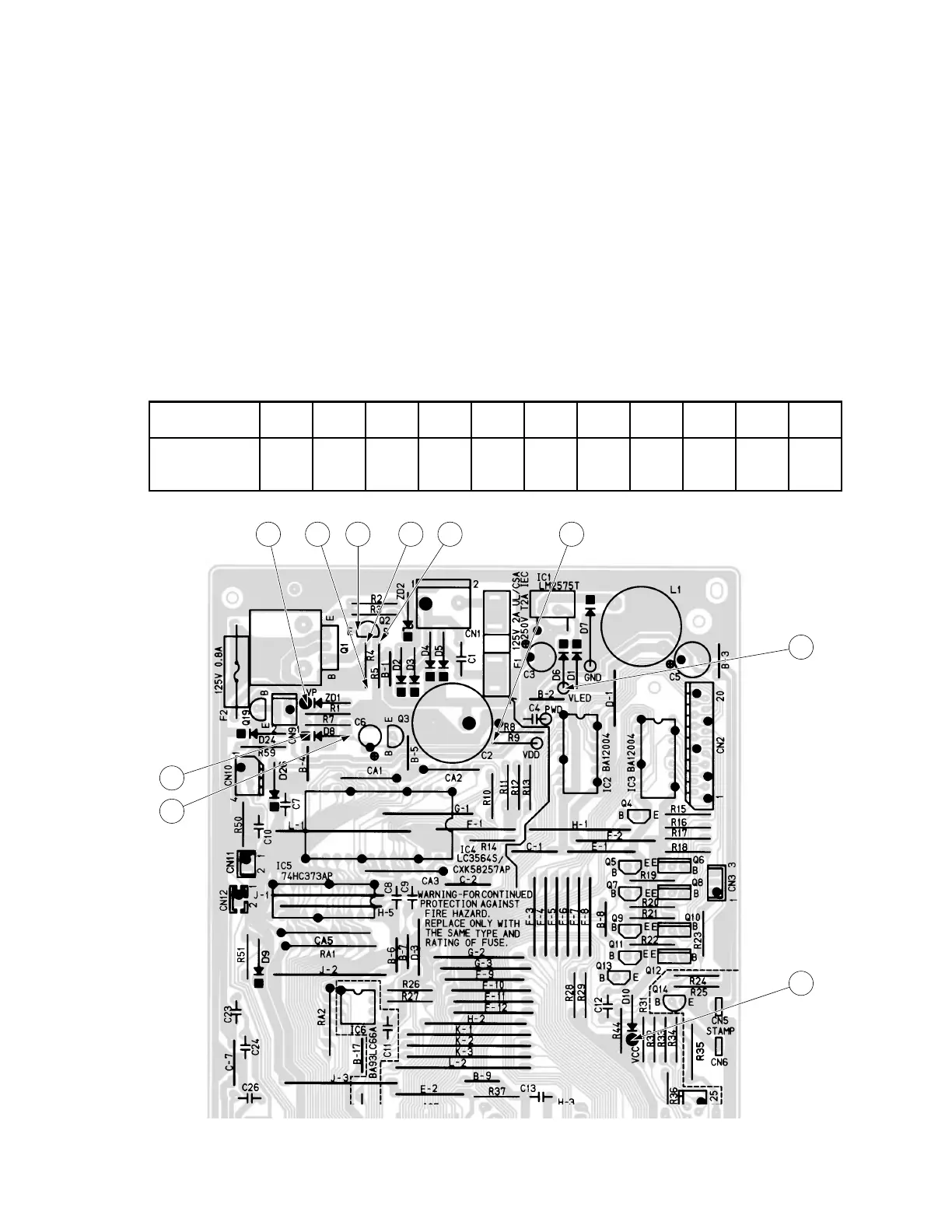
[Voltage and check points in the power supply circuit]
Actual value on the E245-1 PCB [unit : V]
Check point A B C D E F G H I J K
Power on 23.2 V 30 17.9 19 5.9 6.5 4.3 0.0 0 5.6 4.8
(A C)
Voltage check position
BC DE F I
G
H
J
K

 Loading...