— 14 —
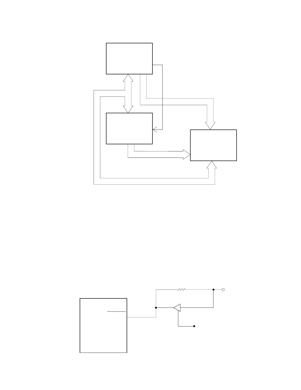
5-4. RAM address
CPU is used port 40 ~ 47 (pin No. 19 ~ 26) for address/data bus.
CPU sends the address A0 ~ A13 to RAM through the IC5. To select the address A0 ~ A7, CPU send
the address AD0 ~ AD7 to IC5. Then CPU sends ASTB (Latch enable) signal to IC5.
IC5 outputs the address A0 ~ A7 after receipt of ASTB signal.
GND
VDD
1 2
3
CPU
RESET
5-5. Initialize IC (Reset IC)
When the voltage level on 60 pin of CPU is not stabilized, CPU doesn’t work properly in rare case.
Therefore, this machine uses the initialize IC for stabilizing the voltage.
Even the voltage level of VDD (2 pin) is changed, 1 pin of initialize IC outputs stabilized 5 volts.
CPU
IC5
74HC373
A0 ~ A7
D0 ~ D7
AD0 ~ AD7
A8 ~ A13
ASTB
RAM
 Loading...