- 14 -
Memory map
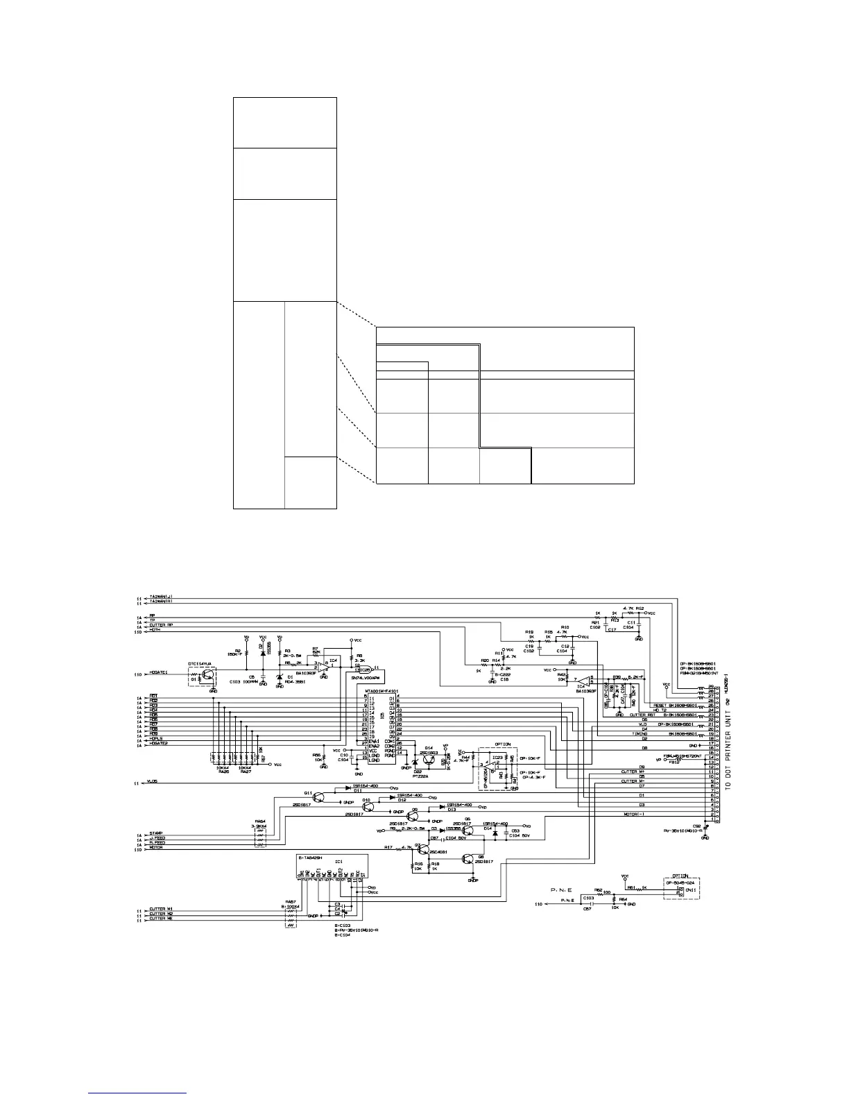
6-7. Printer drive circuit
The printer drive circuit is as follows:
IC5 (MTA001M-F4101) is the head pin driver. And, the Transistors Q6,Q7 and Q8 are the
motor drive circuit. The IC1 (TA8429H) is the auto paper cut driver circuit. For CE-6000, the
auto paper cut drive circuit is not used.
00000h CPU internal memory
Mask ROM 128K
RAM 5K
0FFD0h External I/O Mapping 16bytes
0FFE0h
20000h
RAM1 128 K bytes
40000h
Not used
80000h
Bank area
Flash 1 384 K bytes 16 M bit
(for
A0000h Application 8 M bit
program area) 4 M bit
2 M bytes Bank0 Bank1 Bank2 Bank3 Bank4
00,01 08,09 14,15 20,21 26,27 Block No.
(07,06) (0F,0E) (19,18) (17,16) (1F,1E) (Memory Block)
C0000h
02,03 10,11 16,17 22,23 28,29
(05,04) (0D,0C) (11,10) (15,14) (1D,1C)
E0000h 04,05 12,13 18,19 24,25 30,31
Common area (o3,02) (0B,0A) (09,08) (13,12) (1B,1A)
128 K bytes
Block
06,07
FFFFFh (00,01)
 Loading...