— 14 —
4-4. VCOM DC adjustment
1. General
Perform these adjustments when you replace LCD module or D-PCB.
2. Preparation
(1) AC adaptor or stabilizer.
(2) Photo sensor (S1153)/ Photo sensor amp (C2719)
(3) Digital oscilloscope or AC meter.
(3) B. P. F
NTSC: Center frequency; approx. 60 ± 5 Hz
PAL: Center frequency; approx. 50 ± 5 Hz
3. Adjustment and checking
(1) Boot MENU 1 on the test mode.
1. Turn the camera on while pushing SHIFT and MENU keys.
2. Push SHIFT keys twice then MENU keys rapidly.
(2) Select and execute 50 PERCENT GRAY.
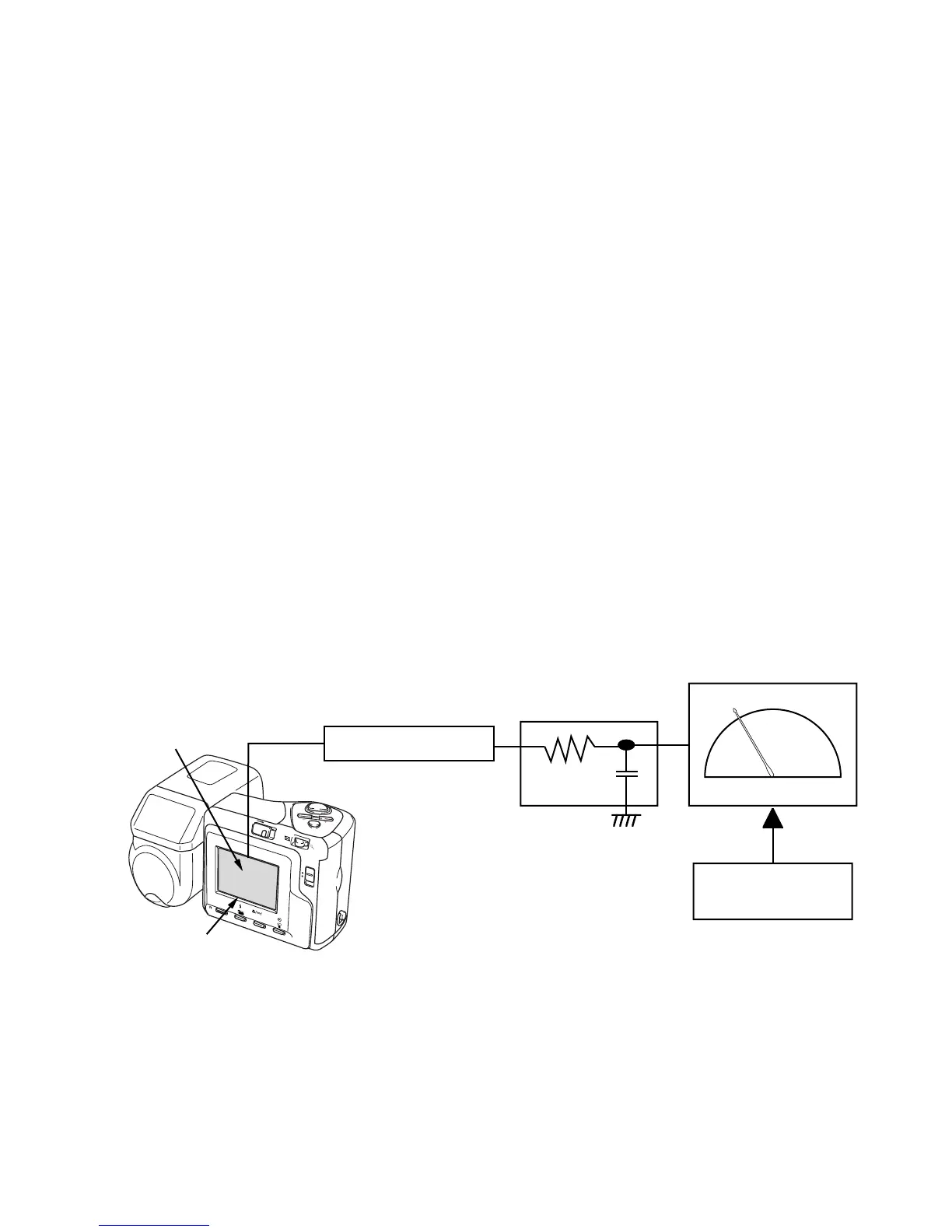
(3) Monitor the Photo Sensor Amp output via a bypass filter with an AC meter and adjust VR321 so that the
meter needle swing is minimum.
Instead of an AC meter, you can use an oscilloscope. In that case, adjust VR321 for minimum ripple
component.
4. Block diagram
CARD
POWER
ON/OFF
W
T
MENU
PLAY
REC
SHIFT
INFO
RESIZE
MF
B.P.F
Photo Sensor Amp
C2719
AC meter
Minimize the swing
of AC meter needle.
QV-2900UX
LCD
Photo diode
S1153
 Loading...