1-7
Cisco Connected Grid Routers 2010 Hardware Installation Guide
OL-21559-01
Chapter 1 Overview of the Router
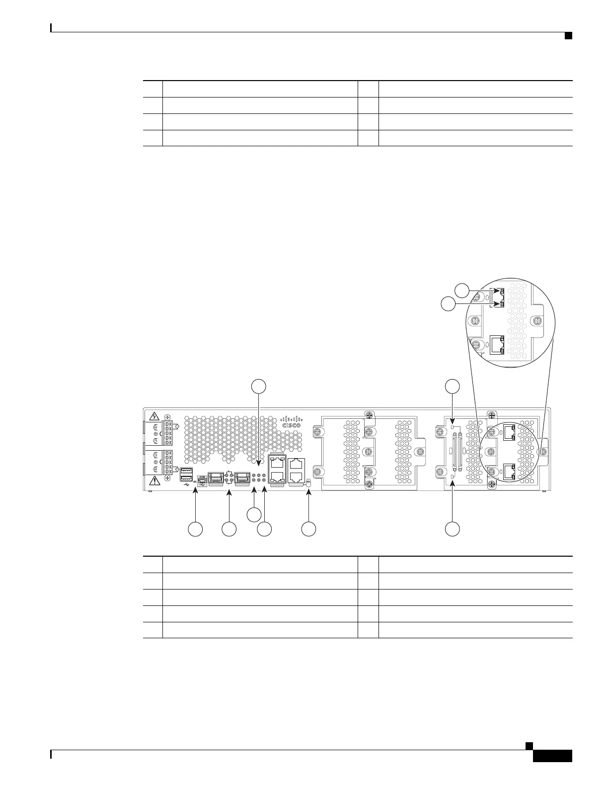
LED Indicators
Figure 1-7 Cable Side View LEDs on the Cisco 2010 CGR
For LED troubleshooting information, including possible trouble causes and corrective actions, see
Table 1-3.
5 SLOT LEDs (slots 0 through 3) 6 Console/USB connection LEDs
7 PSU1/2 LEDs 8 Compact flash slot 1 LED
9 PSU OK LED 10 Compact flash slot 0 LED
1. PSU = Power supply unit
2. ACT = Activity
3. SYS = System
4. SFP = Small form-factor pluggable module slots 0 and 1
5. EN = Enable
6. SPD = Speed
7. GE = Gigabit Ethernet slots 0 and 1
8. LNK = Link
1 PSU
1
OK LED 2 ACT
2
and SYS
3
LEDs
SFP 0/0
GE 0/0
GE 0/1
SFP 0/1
CONSOLE
PSU2
L
N
N
L
+
Lo
-
-
Lo
+
-
HI
+
+
HI
-
Cisco CGR 2010
0
1
EN
SPD
CF
1
PS
2ACT
SYS 0 1
SL
SL
AUX
EN
SLOT 3 SLOT 2 SLOT 1 SLOT 0
CONN CONN
0-3
4-7
GRWIC–8A/8-232
GRWIC–2CE1T1-PRI
CD/LP AL CD/LP AL
P1 P0
PSU1
EN
1
6 8
3
2 5
4
7
GRWIC–2CE1T1-PRI
CD/LP AL CD/LP AL
P1 P0
9
10
277567
1 EN (enable USB console) 2 SFP
1
EN and SPD LEDs
1. SFP = Small form factor pluggable.
3 ACT status and SYS status LEDs 4 Compact flash 0 and 1 (0, bottom, 1, top)
5 PSU1 (bottom), PSU2 (top) 6 EN (enable RJ-45 console)
7 GRWIC serial interface CONN LED 8 GRWIC serial interface CONN LED
9 Dual-port T1/E1 GRWIC CD/LP LED 10 Dual-port T1/E1 GRWIC AL LED
 Loading...