REVIEW DRAFT—CISCO CONFIDENTIAL
5-3
Cisco Connected Grid Routers 2010 Hardware Installation Guide
OL-21559-01
Chapter 5 Installing and Upgrading Internal Modules
Removing and Installing Compact Flash Memory Cards
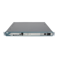
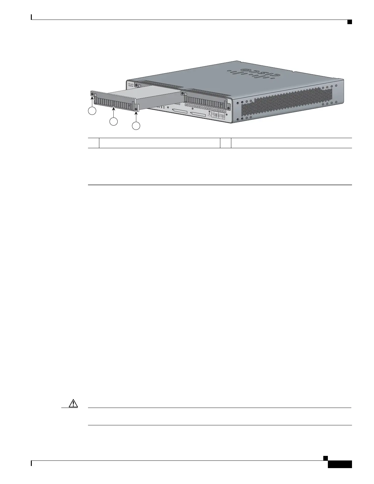
Figure 5-1 Removing the Cisco 2010 CGR Power Supply
Step 3 Insert the replacement power supply into the chassis. See Figure 5-1.
Step 4 Tighten the captive screws that fasten the power supply to the chassis.
Removing and Installing Compact Flash Memory Cards
This section describes installing and replacing compact flash (CF) memory cards in Cisco 2010 CGR
routers. It contains the following sections:
• Preventing Electrostatic Discharge Damage, page 5-3
• Removing a Compact Flash Memory Card, page 5-4
• Installing a Compact Flash Memory Card, page 5-6
Preventing Electrostatic Discharge Damage
Compact flash memory cards are sensitive to electrostatic discharge (ESD) damage, which can occur
when electronic cards or components are handled improperly, results in complete or intermittent failures.
To prevent ESD damage, follow these guidelines:
• Always use an ESD wrist or ankle strap and ensure that it makes good skin contact.
• Connect the equipment end of the strap to an unfinished chassis surface.
• Place a removed compact flash memory card on an antistatic surface or in a static shielding bag. If
the card will be returned to the factory, immediately place it in a static shielding bag.
• Avoid contact between the card and clothing. The wrist strap protects the card from ESD voltages
on the body only; ESD voltages on clothing can still cause damage.
• Do not remove the wrist strap until the installation is complete.
Caution For safety, periodically check the resistance value of the antistatic strap. The measurement should be
between 1 and 10 megohms (Mohms).
1 Power supply 2 Power supply captive screws
277597
PSU1 PSU2
PSU OK
PWR-150W-HV
SYS SPD
SPD SPD
SPD 2 0 1USB
CON
ACT
SFP
0/0
EN
SFP
0/1
EN
GE
0/1
LINK
GE
0/0
LINK
PSU
23 1 CONSOLE
SLOT
CF1
DO NOT REMOVE DURING
NETWORK OPERATION
CF0
DO NOT REMOVE DURING
NETWORK OPERATION
Cisco 2935R
“CAUTION: This unit may have more than one power source.
Disconnect all power sources before servicing to avoid electric chock.”
PS Type
LoV dc
HiV dc
V ac, 50/60 Hz
10A
2A
2A
Input Rating Per Sources
24-60V
100-270V
100-240V ~
PSU1 PSU2
PSU OK
PWR-150W-HV
SYS SPD
SPD SPD
SPD 2 0 1
USB
CON
ACT
SFP
0/1
EN
SFP
0/0
EN
GE
0/1
LINK
GE
0/0
LINK
PSU
231
CONSOLE
SLOT
CF1 CF0
PSU OK
PWR-150W-HV
DO NOT REMOVE DURING
NETWORK OPERATION
DO NOT REMOVE DURING
NETWORK OPERATION
Cisco Connected Grid Router 2000 Series
CAUTION: This unit may have more than
one power source. Disconnect all power
sources before servicing to avoid
electric shock.
PSU OK
PWR-150W-HV
2
1
2
PS
Type
Input Terminal
Symbol
Input Rating
Per Source
Lo V DC
Hi V DC
Lo 24 - 60 V 10A
100-250V 2A
100-240V
~
2A
50-60 Hz
Hi
or
V AC
~
 Loading...