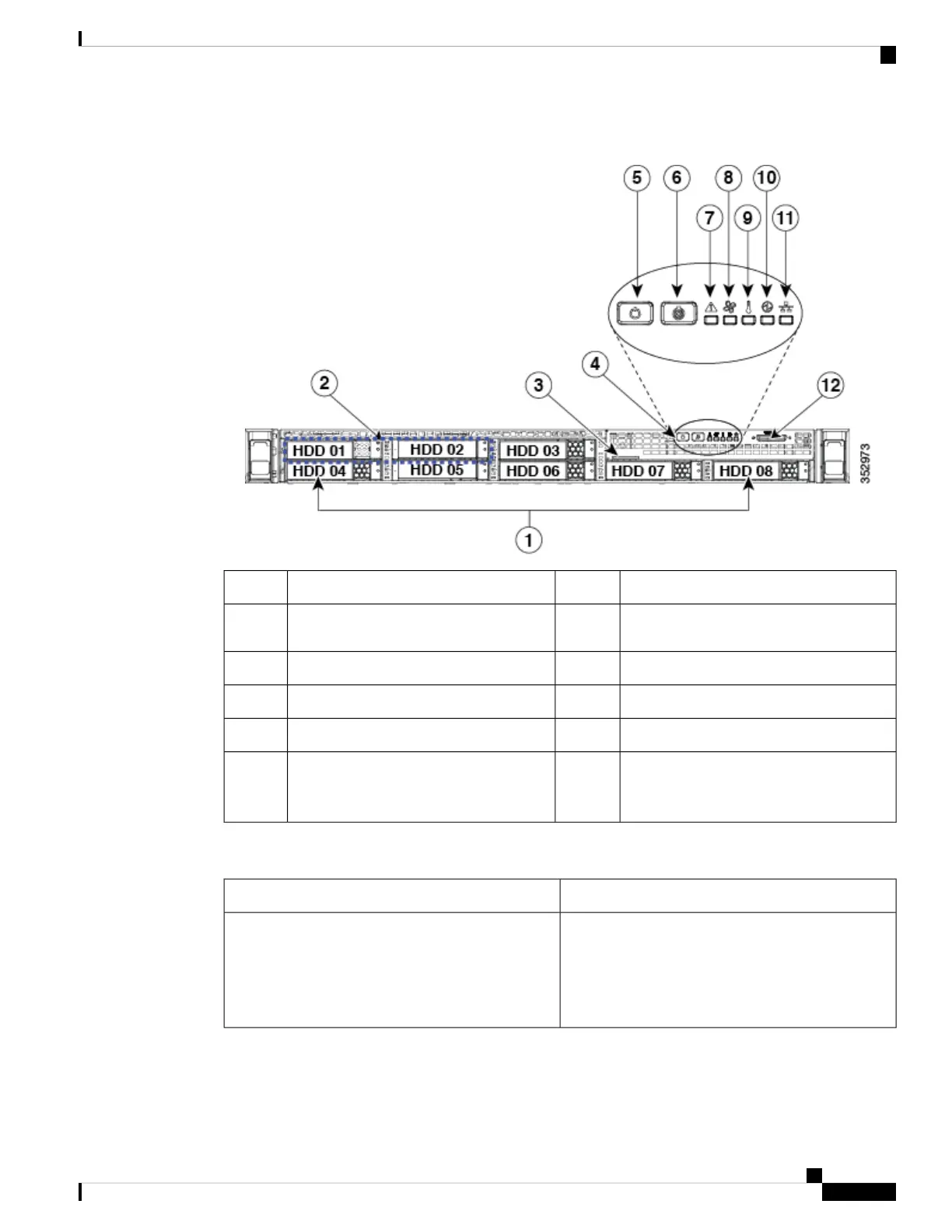
Figure 1: Front Panel LEDs
System status LED7Drive bays 1-8 support SAS/SATA drives1
Fan status LED8Drive bays 1 and 2 support SAS/SATA
and NVMe PCIe solid state drives (SSDs)
2
Temperature status LED9Pull-out asset tag3
Power supply status LED10Operations panel buttons and LEDs4
Network link activity LED11Power button/power status LED5
KVM connector (used with KVM cable that
provides two USB 2.0, one VGA, and one
serial connector)
12Unit identification button/LED6
The following table describes the LEDs located on the front panel of the Cisco SNS-3515 or Cisco SNS-3595
appliance.
Front Panel LEDs
• Off—The hard drive is operating properly.
• Amber—Drive fault detected.
• Amber, blinking—The device is rebuilding.
• Amber, blinking with one-second
interval—Drive locate function activated.
Hard drive fault
Cisco Secure Network Server 3500 Series Appliance Hardware Installation Guide
3
Cisco SNS 3500 Series Appliance Overview
Cisco SNS-3515 or 3595 Appliance Front Panel View