5-41
Cisco 6400 Hardware Installation and Maintenance Guide
OL-2133-02
Chapter 5 Maintaining the Cisco 6400
Replacing a DC Power Entry Module
Replacing a DC Power Entry Module
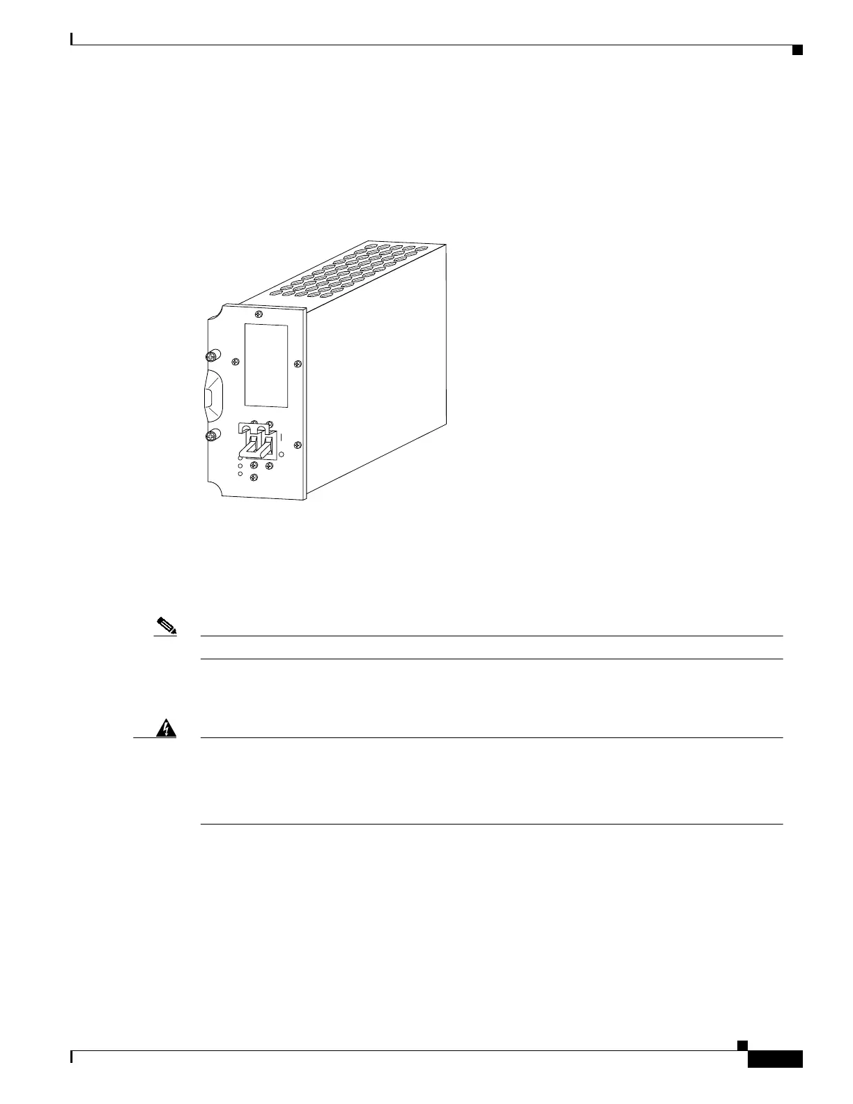
This section describes procedures for removing and installing a DC power entry module (PEM) plug-in
unit in the Cisco 6400 chassis (Figure 5-33).
Figure 5-33 DC Power Entry Module
There are two PEM power bays in the system for redundancy. The PEM power bays are located at the
front left side of the chassis:
• The top bay is wired to power circuit A
• The bottom bay is wired to power circuit B
Note The circuits are identified at the power terminals on the backplane.
The PEMs meet critical safety, isolation, and EMC requirements associated with the connection of the
CO DC-input power distribution system.
Warning
Before working on equipment that is connected to power lines, remove jewelry (including rings,
necklaces, and watches). Metal objects will heat up when connected to power and ground and
can cause serious burns or weld the metal object to the terminals. Translations of this warning
can be found in the
Regulatory Compliance and Safety Information
document that accompanied
this device.
13420
POWER
FAULT
MISWIRE
 Loading...