21
Removing and Replacing Memory SIMMs and the Boot ROM
If any pins are bent, remove the boot ROM, use the needlenose pliers to straighten the pins, and
reinsert the boot ROM as described in Step 7 through Step 9. Note that a broken pin means that the
boot ROM is unusable, and you must order a new one.
If all pins are inserted correctly, and the boot ROM notch is aligned with the socket notch, the boot
ROM is properly installed.
This completes the steps for installing a new Boot ROM. Proceed to the section “Replacing the
Input/Output Controller.”
Replacing the Input/Output Controller
To replace the I/O controller in the router, complete the following steps:
Step 1 Ensure that the router is powered down and its input power cable is disconnected from
the router and the power source. Refer to the section “Powering Down the Router and
Disconnecting Input Power” earlier in this document.
Step 2 Attach an ESD-preventative wrist strap between you and an unfinished chassis surface.
Step 3 Using both hands, grasp the I/O controller by its metal carrier edges and orient the I/O
controller so that its printed circuit board components are upward (refer to Figure 8).
Caution Handle the I/O controller by the carrier edges and handle only; never touch the printed
circuit board components or connector pins.
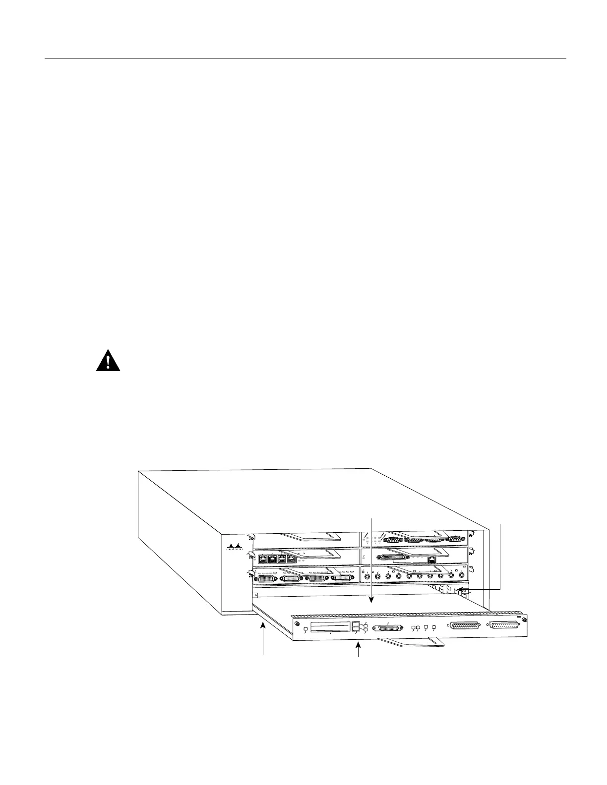
Step 4 Align the left and right edge of the I/O controller between the I/O controller slot guides
(refer to Figure 18).
Figure 18 Aligning the I/O Controller’s Printed Circuit Board between the Slot Guides
H6421
ETHERNET 10BT
ENABLED
0
2
1
3
LINK
0
1
2
3
FAST SERIAL
EN
TD
TC
RD
RC
LB
CD
TD
TC
RD
RC
LB
CD
TD
TC
RD
RC
LB
CD
TD
TC
RD
RC
LB
CD
ENABLED
MII
LINK
RJ45
FAST ETHERNET
0
TOKEN RING
0
1
2
3
0
2
4
6
1
3
5
Metal carrier
Printed circuit board
ETHERNET-10BFL
EN
RX
0
1
2
3
4
TX
RX
TX
RX
TX
RX
TX
RX
TX
Slot guides
I/O controller
FAST ETHERNET INPUT/OUTPUT CONTROLLER
ENABLED
PCMCIA
EJECT
SLOT 0
FE
ENABLE
FE LINK
CPU RESET
1O POWER
OK
SLOT 1
FE MII
Cisco 7200
Series
 Loading...


