damage components on the printed circuit board as you slide the I/O controller into its chassis slot.
mate with the router midplane.
Note The I/O controller is not fully seated in the router midplane until you tighten its captive
installation screws (use a number 2 Phillips screwdriver).
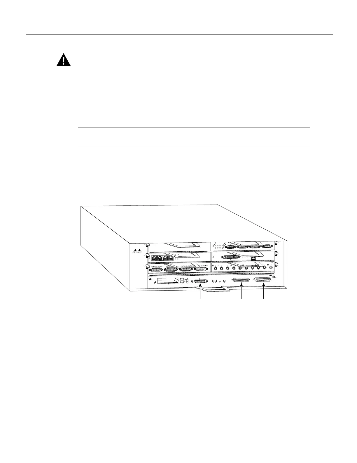
Step 7 Connect the cables to the I/O controller’s console, auxiliary, and Fast Ethernet (if present)
ports (refer to Figure 19).
Figure 19 Input/Output Controller Ports, Handle, and Captive Installation Screws
Step 8
Replace Flash memory cards (if present) in the I/O controller’s PCMCIA slots. Refer to
the section “Installing and Removing a Flash Memory Card” later in this document.
This completes the procedure for replacing the I/O controller in a Cisco 7200 series router. Proceed
to the section “Replacing the Network Processing Engine.”
Replacing the Network Processing Engine
To replace the network processing engine in the router, complete the following steps:
Step 1 Ensure that the router is powered down and its input power cable is disconnected from
the router and the power source. Refer to the section “Powering Down the Router and
Disconnecting Input Power” earlier in this document.
Step 2 Attach an ESD-preventative wrist strap between you and an unfinished chassis surface.
 Loading...


