11
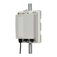
Cisco Aironet Series Power Injectors AIR-PWRINJ-60RGD1= and AIR-PWRINJ-60RGD2= Installation Instructions
Connecting Data and Power to the Injector
Connecting Data and Power to the Injector
Warning
To reduce the risk of fire, use only No. 26 AWG or larger telecommunication line cord.
Statement 1023
Warning
To avoid electric shock, do not connect safety extra-low voltage (SELV) circuits to telephone-network
voltage (TNV) circuits. LAN ports contain SELV circuits, and WAN ports contain TNV circuits. Some
LAN and WAN ports both use RJ-45 connectors. Use caution when connecting cables.
Statement 1021
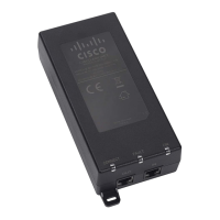
To connect the data cables and to power up the power injector, follow these steps:
Step 1 Plug a shielded outdoor rated Ethernet cable, using the factory-shipped waterproof RJ45 connector, into
the DATA PWR OUT port on the power injector. Assembling of the waterproof RJ45 connector is shown
in Figure 6.
Step 2 Plug the other end of the Ethernet cable into the Ethernet Port on the access point.
Note For detailed information about connecting the Ethernet cable to an access point, see the
Hardware Installation Guide for that access point.
Step 3 Plug a shielded outdoor rated Ethernet cable, using the factory-shipped waterproof RJ45 connector, into
the DATA IN port on the power injector. Assembling of the waterproof RJ45 connector is shown in
Figure 6.
Step 4 Plug the other end of the Ethernet cable into your Ethernet switch, hub, or network.
Step 5 Plug in the AC power cord. For the RGD1=, plug the AC connector into suitable a AC receptacle. For
the RGD2 = follow local codes to terminate the three wires of the AC cable. For AC power cord and wire
sizes, see Table 1.
Step 6 Connect the other end of the power cord into a 100-VAC to 240-VAC power source
Table 1 AC Power Cord and Wire Sizes
Type AC Cord Sizes Individual AC Wire Sizes
RGD2= 6.8mm +/-0.4mm 0.75mm/3C
RGD1= (for reference only) 8mm +/-0.4mm 18AWG/x3C
 Loading...