• Observe the polarity—Unlike the polarity labels of the –48 VDC power supply (ground, positive, negative),
the polarity labels on the +24 VDC are ground, negative, positive as shown in xref fig from right to left
as they appear on the actual power supply unit.
• The ground (GND) lead is always installed first and removed last.
• The +24 VDC power supply uses a spring loaded terminal block; therefore have the recommended
screwdriver size available.
• Review the diagrams to see how the wire is stripped and how the screwdriver is inserted at an angle into
the terminal block.
• Have the following equipment available to install and remove the +24 VDC power supply:
• 3.5mm flat-blade screwdriver
• 8-gauge wire
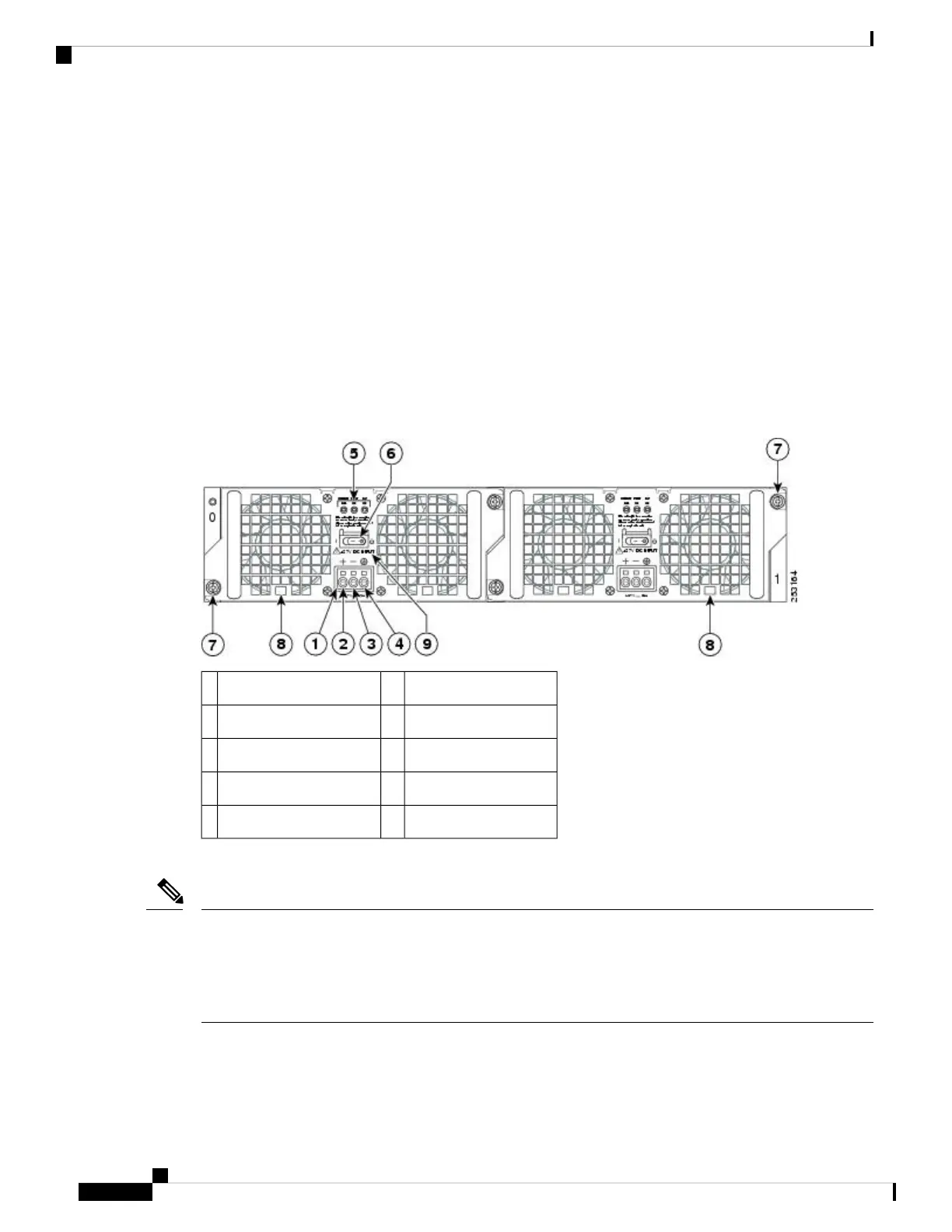
The following figure shows the +24 VDC power supply for the Cisco ASR 1002 Router.
Figure 59: +24 VDC Power Supply for the Cisco ASR 1002 Router
Standby/On switch6+24 VDC terminal block1
Captive fastener7Positive (+) lead2
Power supply tabs8Negative (-) lead3
+27 VDC INPUT label9Ground (GND) lead4
——Power supply LEDs5
This section describes how to connect the +24 VDC power supply in the Cisco ASR 1002 Router.
The color coding of the +24 VDC input power supply leads depends on the color coding of the +24 VDC
power source at your site. Typically, green or green/yellow is used for ground. Make certain the lead color
coding you choose for the +24 VDC input power supply matches lead color coding used at the +24 VDC
power source. Most commonly used wire color-coding is red for positive (+) lead and black for negative (–)
lead.
Note
Removing and Replacing FRUs from the Cisco ASR 1000 Series Routers
92
Removing and Replacing FRUs from the Cisco ASR 1000 Series Routers
Replacing the +24 VDC Power Supply in Cisco ASR 1002 Router

 Loading...


