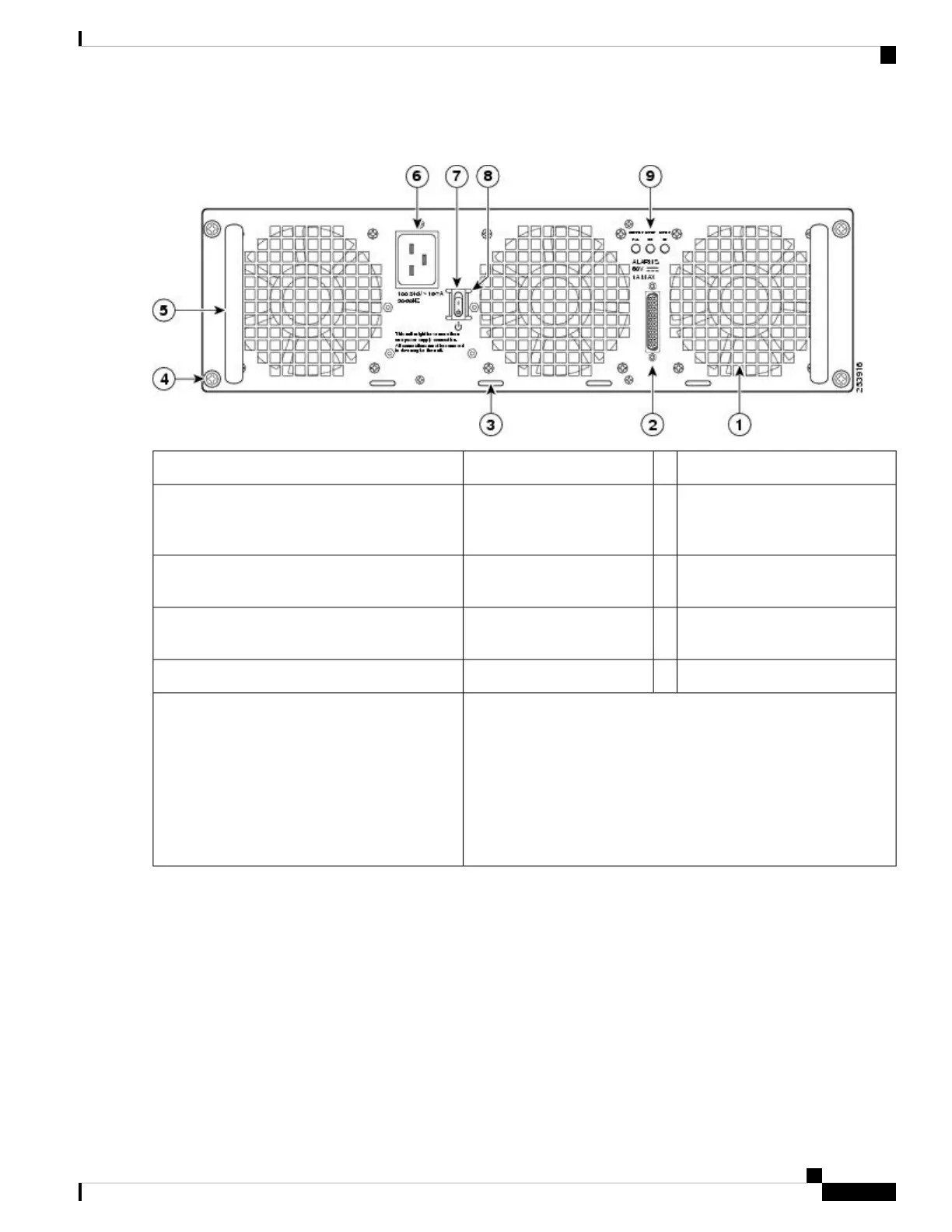
Figure 67: Cisco ASR 1013 Router AC Power Inlet and Standby Switch
AC power inlet6AC power supply fan1
AC power supply standby switch.
A standby switch is not considered
a disconnect.
7DB-25 alarm connector*2
Protective sides around the
standby switch
8Cable tie wrap tabs3
AC power supply LEDs9AC power supply captive
screws
4
——AC power supply handle5
*For information about the DB-25 alarm
connector, how it works, and Cisco ASR 1000
series route processor LEDs, see the xref section.
Note: Shielded cables must be used to connect to
the DB-25 alarm connector on both the AC and
DC power supplies, in order to comply with
FCC/EN55022/CISPR22 Class A emissions
requirements.
Step 4 Unplug the power cable from the AC inlet on the back of the power supply and the power source.
Step 5 Unscrew the power supply captive screws.
The Cisco ASR 1013 router has two power zones, each containing two power supplies for a redundant system.
Power supplies must be installed in the chassis at all times to ensure sufficient cooling. The system fans are
inside the power supply units and must spin for cooling. Because all the system fans can be powered by one
power supply, the second power supply unit does not have to be powered on, but it must be installed.
Note
If you remove a power supply, the system can run for a maximum of five minutes before the system shuts
down. The fans and power elements are independent within the power supply. Therefore, it is not required that
the replacement power supply be energized within five minutes. The only requirement is that the power supply
be installed in the chassis, which energizes the fans and maintains proper system cooling.
Caution
Removing and Replacing FRUs from the Cisco ASR 1000 Series Routers
99
Removing and Replacing FRUs from the Cisco ASR 1000 Series Routers
Removing the AC Power Supply from Cisco ASR 1013 Router

 Loading...


