5-3
Cisco ASR 9001 and Cisco ASR 9001-S Routers Hardware Installation Guide
OL-26701-02
Chapter 5 Replacing Cisco ASR 9001 Router Components
Removing and Replacing AC or DC Power System Components
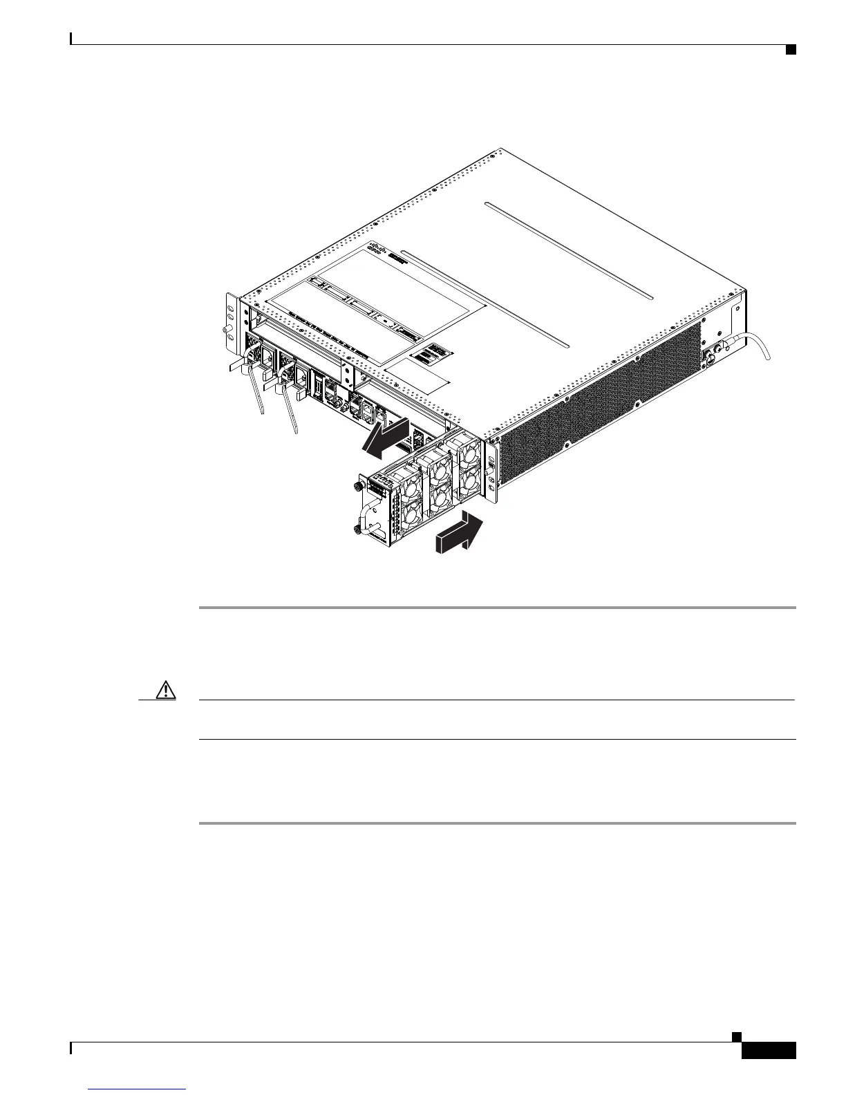
Figure 5-1 Removing or Installing the Fan Tray on the Cisco ASR 9000 Series Router Chassis
To install a fan tray into the chassis:
Step 1 Lift the fan tray (with two hands) and slide it halfway into the module bay.
Step 2 Slowly push the fan tray into the chassis until it mates with the backplane connector at the back of the
module bay.
Caution To prevent damage to the connectors, do not use excessive force when inserting the fan tray into the
chassis.
Step 3 Tighten the captive screw(s) on the fan tray to a torque of 10 +/–1 in-lb to secure it to the chassis.
Step 4 Verify that the (green) OK status indicator on the front of the fan tray goes on. If the OK indicator does
not light, see the “Troubleshooting the Cooling Subsystem” section on page 4-18.
Removing and Replacing AC or DC Power System Components
This section contains removal and replacement procedures for the AC and DC power systems used in the
Cisco ASR 9000 Series Router.
332382

 Loading...


