Grounding Receptacle LocationModel Number
Top rear right side of the chassis (Figure 63: NEBS Bonding and Grounding for
the Cisco ASR 9006 Router, on page 66).
Cisco ASR 9006 Router
Bottom rear right side and rear left side of the chassis (Figure 64: NEBS Bonding
and Grounding for the Cisco ASR 9904 Router, on page 66).
Cisco ASR 9904 Router
Bottom rear and left side of the chassis (Figure 65: NEBS Bonding and Grounding
for the Cisco ASR 9906 Router).
Cisco ASR 9906 Router
Top rear right side of the chassis (Figure 66: NEBS Bonding and Grounding for
the Cisco ASR 9922 Router, on page 67).
Cisco ASR 9922 Router
Bottom rear right side of the chassis (Figure 67: NEBS Bonding and Grounding
for the Cisco ASR 9912 Router, on page 68).
Cisco ASR 9912 Router
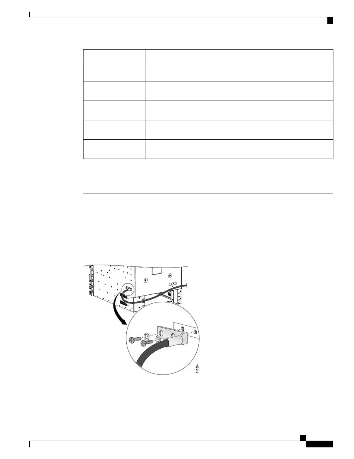
Follow these steps to attach a grounding cable lug to the router:
Procedure
Step 1 Insert the grounding screws (10-32 round-head) through the locking washers (ideally nickel-plated brass) and
into the threaded grounding receptacle (has two M6 bolt holes with 0.625 to 0.75 spacing between them). The
wire receptacle is large enough to accept a #6 AWG or larger multi-strand copper wire.
Step 2 Tighten the grounding screws securely to the receptacles.
Step 3 Prepare the other end of the grounding wire and connect it to the appropriate grounding point at your site to
ensure an adequate earth ground.
Figure 62: NEBS Bonding and Grounding for the Cisco ASR 9010 Router
Unpacking and Installing the Chassis
65
Unpacking and Installing the Chassis
Supplemental Bonding and Grounding Connections
 Loading...


