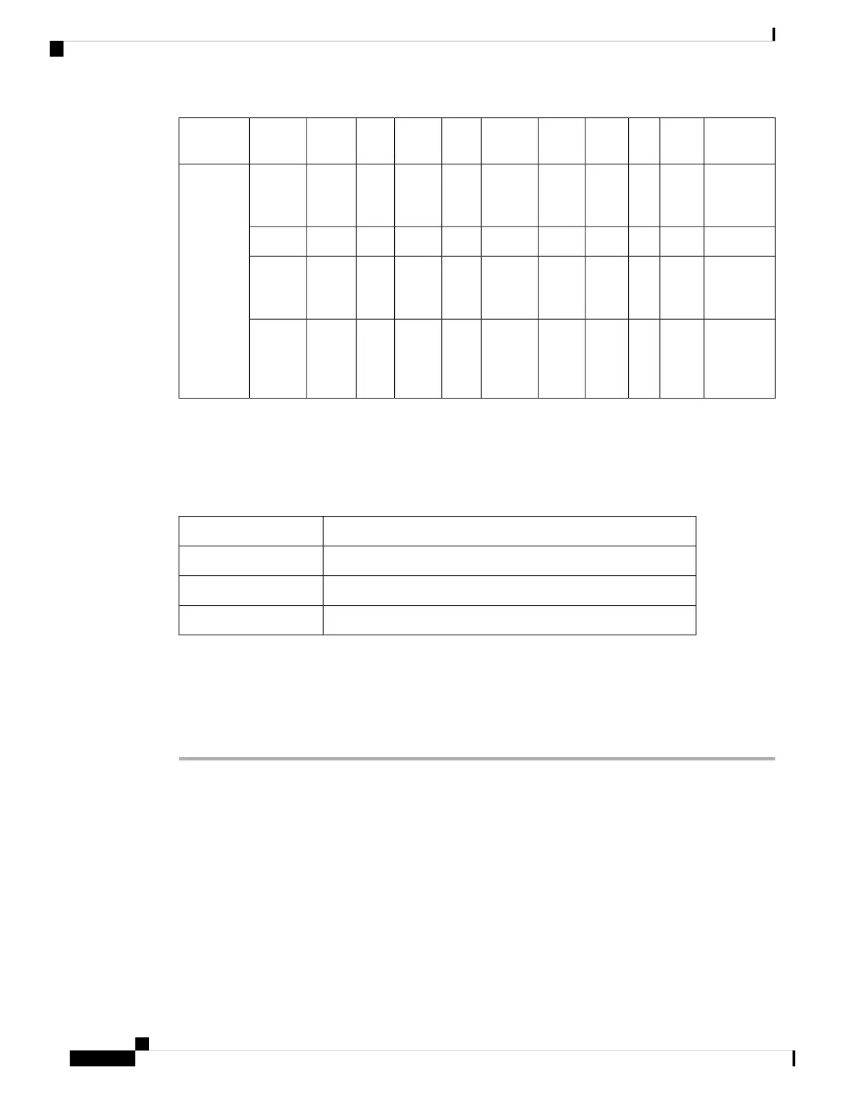
NotesPoE-outGbE
PHY
SFP
Module
Ethernet
mGig
AUX
Radio
dBmRadio
1
dBmRadio 0PoE-in/DC
Input
SKU
Serving
radios
disabled
NNN1Genabled—disabled—disabled.3afC9124AXE
Tri-Radio
mode
-NNN1Genabled—disabled—disabled.3at
PoE output
is 802.3af
compliant
15.4WYY2.5Genabled242x2242x2.3bt /
UPOE
using DC
power
source
≥60W
15.4WYY2.5Genabled242x2242x2DC
input
Connecting a Power Injector
The AP supports the following power injectors:
Table 13: Supporting Power Injectors
DescriptionPower Source
60W rated outdoor power injector, with North America AC plugAIR-PWRINJ-60RGD1=
60W rated outdoor power injector, global version without AC plugAIR-PWRINJ-60RGD2=
30W rated single-port PoE injectorAIR-PWRINJ6=
The power injector provides DC voltage to the AP over the Ethernet cable and supports a total end-to-end
Ethernet cable length of 100 m (328 ft) from the switch to the AP.
When an optional power injector powers your AP, follow these steps to complete the installation:
Procedure
Step 1 Before applying PoE to the AP, ensure that the AP is grounded (see Grounding the Access Point, on page
66).
Step 2 Identify the components needed for the installation, see the Typical Access Point Installation Components,
on page 32.
Step 3 Connect a CAT5e or better Ethernet cable from your wired LAN network to the power injector.
To reduce the risk of fire, use only No. 24 AWG or larger telecommunication line cord.
Statement 1023
Danger
The installer is responsible for ensuring that powering the AP from this type of power injector is
allowed by local and/or national safety and telecommunications equipment standards.
Note
Cisco Catalyst 9124AX Series Outdoor Access Point Hardware Installation Guide
68
Installation Overview
Connecting a Power Injector
 Loading...