EasyManuals Logo
Home>Cisco>Network Router>C921-4P

Cisco C921-4P User Manual

Cisco C921-4P
38 pages
To Next Page IconTo Next Page
To Previous Page IconTo Previous Page
Page #26 background imageLoading...
Page #26 background image
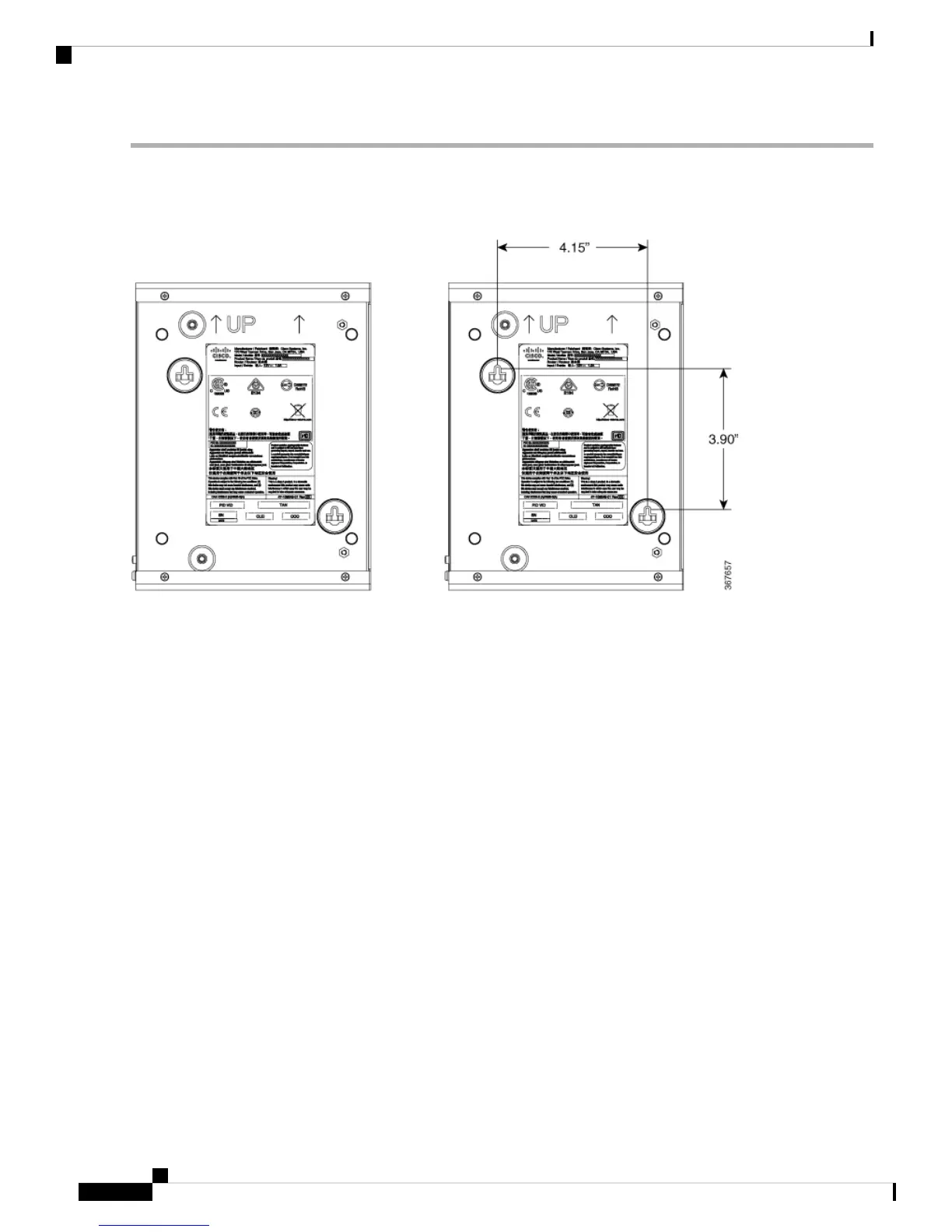
Step 1 Determine the required distance between mounting holes on the router. For Cisco 900 routers, the distance between
mounting holes is 4.15 inches. Figure below shows the wall-mount holes located on the underside of the router.
Figure 15: Router with Wall-mount Holes on the Underside
Step 2 Use a 0.144-inch (3.7 mm) or a #27 drill bit to drill a hole in the wall.
Step 3 Insert the screws, with anchors, into the wall. Leave 1/8 inch (0.32 cm) between the screw head and the wall.
Hardware Installation Guide for the Cisco 900 Series Integrated Services Router
22
Install and Connect the Router
Wall Mount

Questions and Answers:

Question and Answer IconNeed help?

Do you have a question about the Cisco C921-4P and is the answer not in the manual?

Cisco C921-4P Specifications

General IconGeneral
Switch typeManaged
Quality of Service (QoS) supportYes
USB 2.0 ports quantity1
Basic switching RJ-45 Ethernet ports type-
Basic switching RJ-45 Ethernet ports quantity4
10G supportNo
Networking standardsIEEE 802.1D
Product colorBlack
Electromagnetic compatibility47CFR, AS/NZS CISPR22 2, CISPR22, EN55022, ICES003, EN61000-3-2, KCC, EN55024, KN24
Flash memory2048 MB
Internal memory1024 MB
MAC address table- entries
AC input voltage100 - 240 V
AC input frequency50 - 60 Hz
Storage temperature (T-T)-40 - 70 °C
Operating temperature (T-T)0 - 50 °C
Operating relative humidity (H-H)5 - 95 %
Security algorithms802.1x RADIUS
Harmonized System (HS) code85176990
Weight and Dimensions IconWeight and Dimensions
Depth241.3 mm
Width228.6 mm
Height43.2 mm
Weight1200 g

Related product manuals