Chapter 6: VLANs and Trunking 107
Section 6-5
To configure a private edge VLAN, select the interface and type the command port
protected. To verify that a port is in protected mode, use the command show port
protected.
Verifying Private VLAN Operation
After configuring private VLANs, use the following commands to verify the operation:
show vlan private-vlan type
show interface private-vlan mapping
show interface type mod/port switchport
Note A number of guidelines and restrictions apply to private VLANs. For a complete
list of these items, go to http://www.tinyurl.com/cka68e.
Feature Example
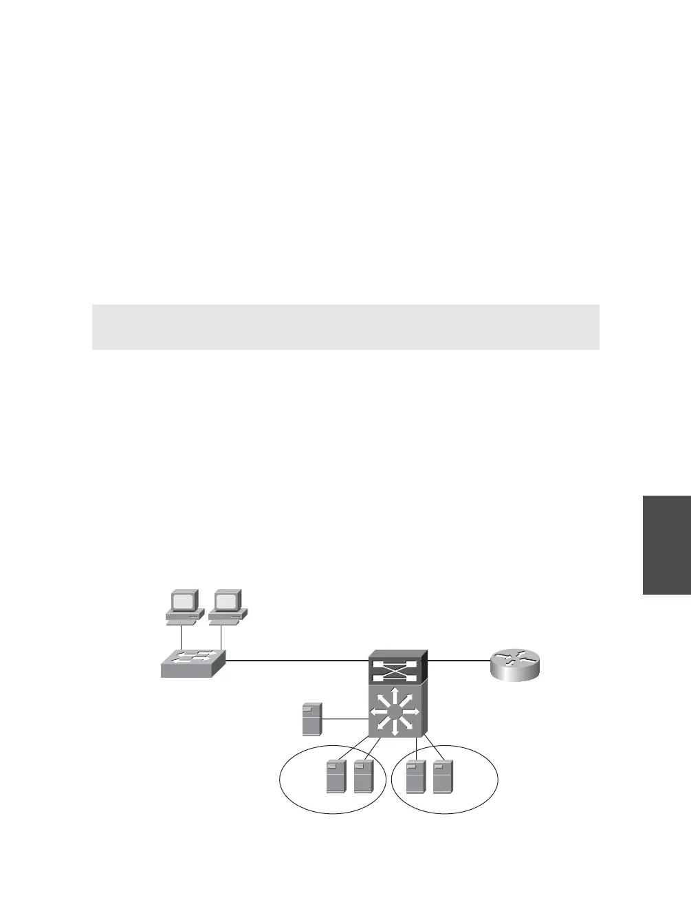
Figure 6-3 shows the network diagram for a working private VLAN configuration exam-
ple. In this example, the switch Access_1 is configured with ports 1 and 2 as protected
ports both in VLAN 10. The VLAN 10 server on Distribution_1 is also in VLAN 10.
This enables the PCs to connect to the server but not one another. Also on the distribu-
tion switch, private VLAN 90 has been created with a community VLAN 901 and an
isolated VLAN 900. Server 2 in port 3/46 and Server 3 in port 3/48 are placed in the
community VLAN, and servers connected to ports 3/1 and 3/2 are to be placed in the
isolated VLAN. All these devices are mapped to the router connected to port 1/2 and
the MSFC port 15/1 for interface VLAN 90.
F 0/1 F 0/2
G 0/1
1/1 1/2 G 2/1
10.10.90.2
3/1
3/2 3/46
3/48
VLAN 10 Server
10.10.10.1
10.10.10.100
10.10.10.101
Access_1
Distribution_1
10.10.90.5
10.10.90.6
10.10.90.7
10.10.90.8
Isolated VLAN 900 Community VLAN 901
Figure 6-3 Network Diagram for Private VLAN Configuration
 Loading...