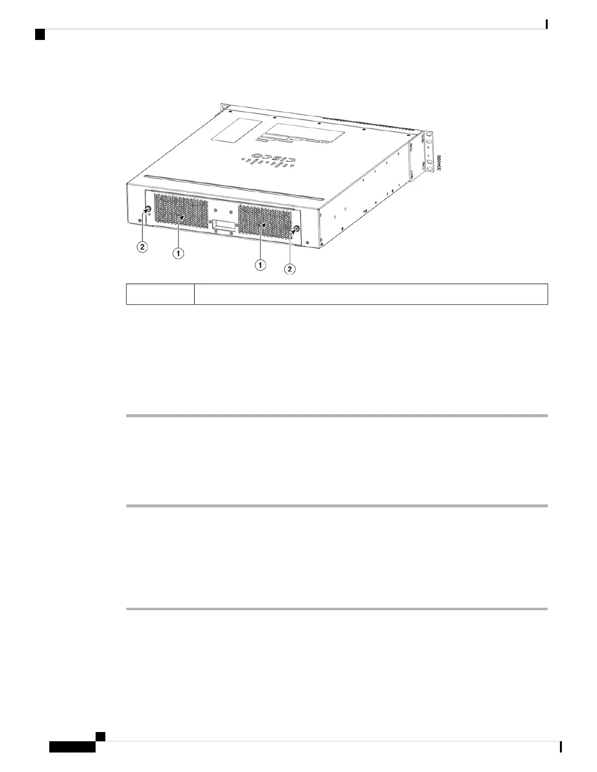
Figure 30: Fan Tray Location
Location of fan tray1
Step 2 Loosen the fan tray captive installation screw by turning it counterclockwise.
Step 3 Grasp the fan tray, and pull it outward; gently move side to side, if necessary, to unseat the fan tray power
connector from the backplane.
When removing the fan tray, keep your hands and fingers away from the spinning fan blades. Let
the fan blades stop completely before you remove the fan tray.
Caution
Step 4 Pull the fan tray clear of the chassis, and set it aside.
Installing the Fan Tray
Procedure
Step 1 Position the fan tray with the captive installation screws in front of the fan tray cavity at the rear of the chassis.
Step 2 Place the fan tray into the chassis cavity so that the pin on the fan tray assembly is aligned with the hole on
the chassis. .
Step 3 Push the fan tray into the chassis until the power connector seats in the backplane and the captive installation
screw make contact with the chassis.
Step 4 Tighten the captive installation screws.
Related Topics
Cooling with the Fan Tray , on page 23
Catalyst 6840-X Switch Series Hardware Installation Guide
62
Replacing the Fan Tray
Installing the Fan Tray
 Loading...