Installing a DC-Input Power Supply Module
When installing a DC-input power supply module, you will need access to the terminal block of the power
supply module in order to connect the DC-input wires. If the front panel of the chassis has limited access
because of other interfering cables, consider connecting the DC-input wires to the terminal block, before you
install the power supply module in the chassis. If you do have clear access to the terminal block, you can
install the power supply module in the chassis first and then connect the DC-input wires.
The procedure to install the module in the chassis and the procedure to connect the DC-input wires have been
described in Installing a DC-Input Power Supply Module in the Chassis, on page 117 and Connecting the
DC-Input Wires, on page 119. You can complete either task first and then move on to the next, and finally
power up the power supply module.
Installing a DC-Input Power Supply Module in the Chassis
To install a DC-input power supply module in the chassis, follow the steps described here.
Before you begin
Only trained and qualified personnel should be allowed to install, replace, or service this equipment. Statement
1030
Warning
No user-serviceable parts inside. Do not open. Statement 1073
Warning
Procedure
Step 1 Remove the power supply blank cover from the chassis, if one is installed.
Step 2 Remove the new or replacement module from its packaging.
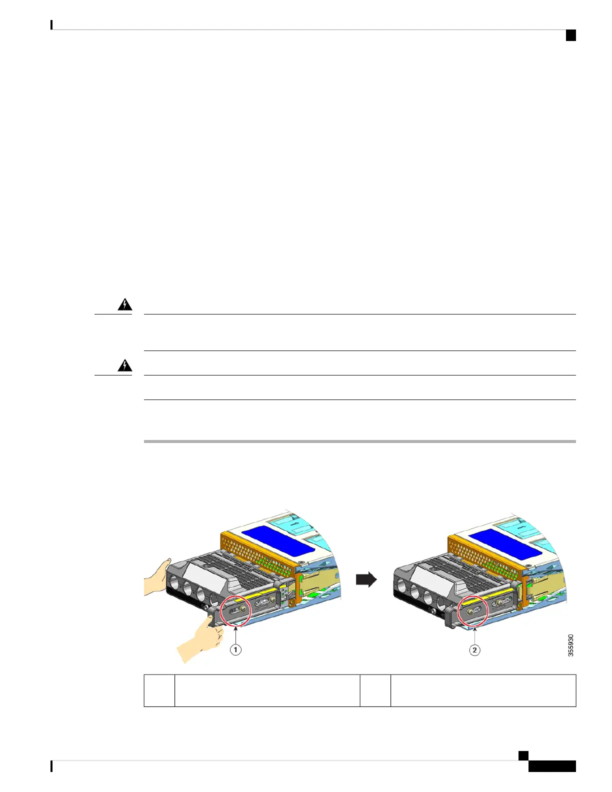
Step 3 Grasp the module with one hand. With your other hand, push in the latch on the module.
Position of the nut on the side of the release
latch after the latch is pushed in.
2Position of the nut on the side of the release
latch before the latch is pushed in
1
Cisco Catalyst 9400 Series Switches Hardware Installation Guide
117
Removing and Replacing FRUs
Installing a DC-Input Power Supply Module
 Loading...