To maintain proper air circulation through the switch chassis, we recommend that you maintain a minimum
space of 6 inches (15 cm) between a wall and the chassis and power supply unit air intakes or a wall and the
chassis and power supply unit hot air exhausts. In situations where the switch chassis are installed in adjacent
racks, you should allow a minimum space of 12 inches (30.5 cm) between the air intake of one chassis and
the hot air exhaust of another chassis. Failure to maintain adequate spacing between chassis may cause the
switch chassis that is drawing in the hot exhaust air to overheat and fail.
Note
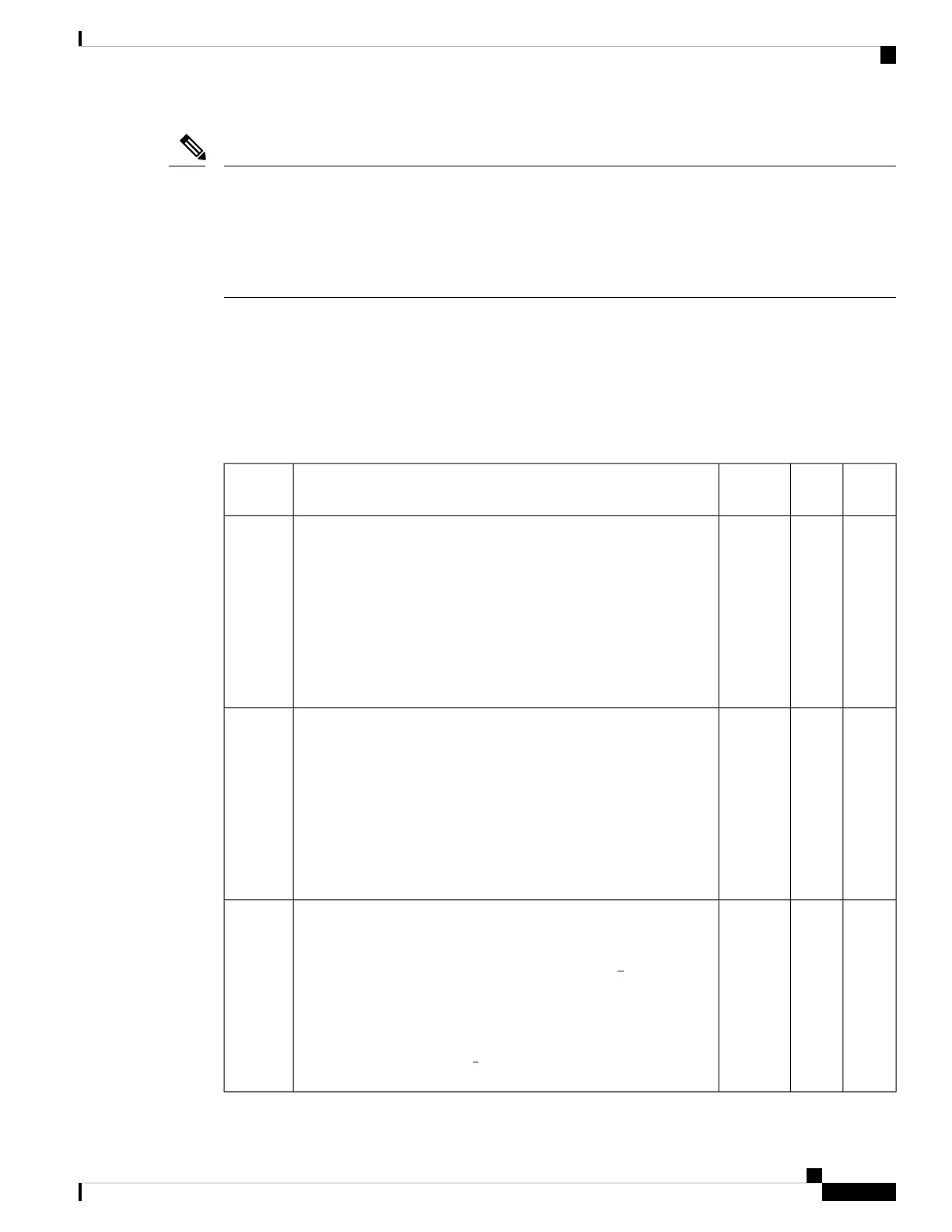
Site Preparation Checklist
The following table lists the site-planning activities that you should perform prior to installing the switch.
Completing each activity helps ensure a successful switch installation.
Table 5: Site Preparation Checklist
DateTimeVerified
By
ActivityTask No.
Space evaluation
• Space and layout
• Floor covering
• Impact and vibration
• Lighting
• Maintenance access
1
Environmental evaluation
• Ambient temperature
• Humidity
• Altitude
• Atmospheric contamination
• Airflow
2
Power evaluation
• Input power type
• Power receptacles (Depends on power supply)
1
• Receptacle proximity to the equipment.
• Dedicated (separate) circuits for redundant power supplies.
• UPS for power failures
2
3
Cisco Catalyst 9400 Series Switches Hardware Installation Guide
43
Preparing for Installation
Site Preparation Checklist
 Loading...