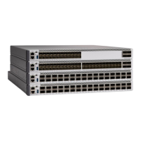
Rear View of a Cisco Catalyst 9606R
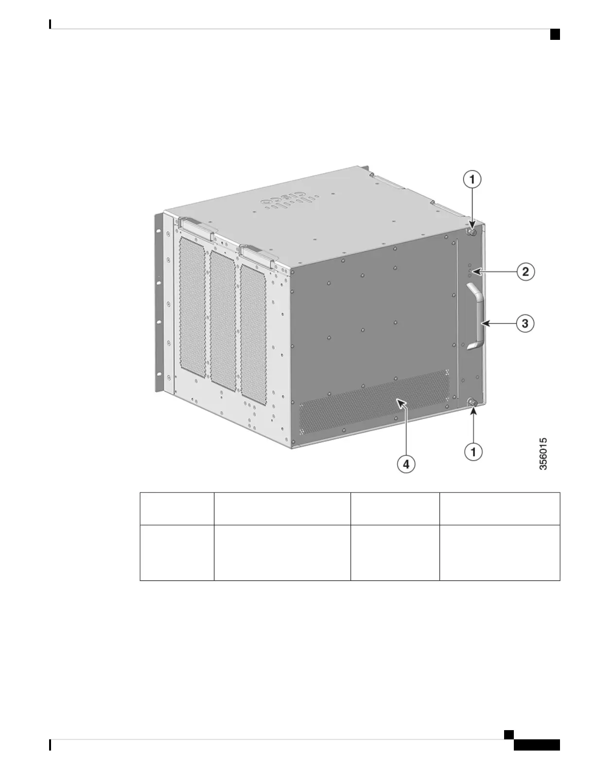
The figure shows a rear view of the chassis, with the major components identified:
Figure 2: Rear View of a Cisco Catalyst 9606R
Fan tray assembly handle3Captive installation screws to
remove the fan tray assembly.
1
Rear exhaust for the power
supply modules
4Blue beacon LED on the rear
panel of the fan tray (always
matches the blue beacon on the
front panel of the fan tray)
2
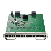
Fan Tray Assembly
The fan tray assembly (C9606-FAN) in Cisco Catalyst 9600 Series Switches consists of a fan tray and a
connector that is attached to the fan tray. It is responsible for cooling the entire chassis and interfacing with
environmental monitors to trigger alarms when conditions exceed thresholds. The fan tray provides cooling
Cisco Catalyst 9600 Series Switches Hardware Installation Guide
3
Product Overview
Fan Tray Assembly
 Loading...