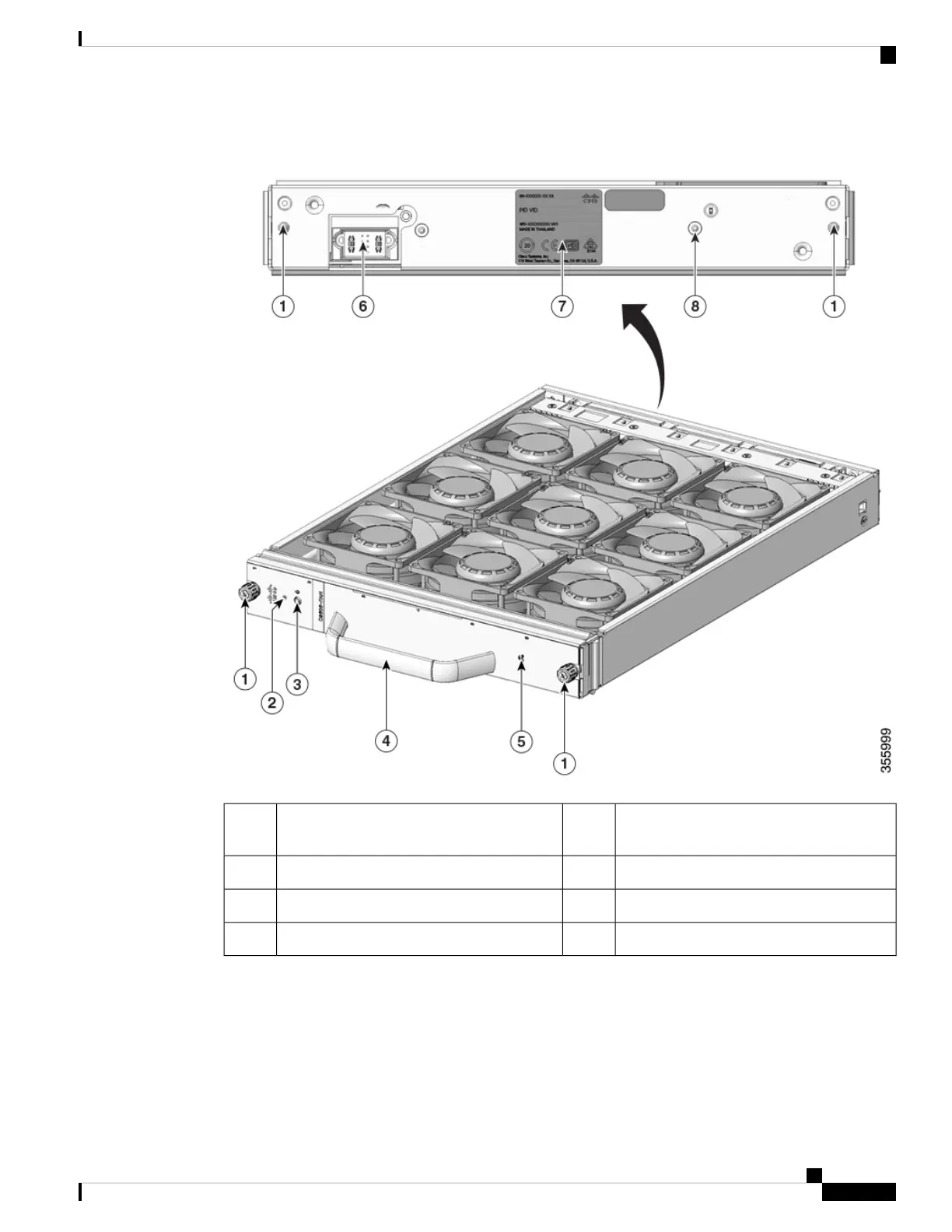
Figure 3: Fan Tray Assembly
Fan tray RFID5Captive installation screws on the front and
the rear of the fan tray.
1
Fan tray connector6Fan status LED2
Fan tray serial number7Switch to turn on the Blue Beacon LED.3
Blue beacon LED on the rear of the fan tray8Front fan tray handle.4
High Availability
To ensure high availability, the system is designed to respond to fan failures by either minimising impact or
by compensating and operating at a worst case scenario specification.
• If a single fan fails, the remaining fans in the row compensate with increased speed.
Cisco Catalyst 9600 Series Switches Hardware Installation Guide
5
Product Overview
High Availability
 Loading...