Step 4 Assemble the mounting arm to connect the access point bracket and the wall mounting flange.
Hand tighten all screws and nuts. See Figure 19: Exploded View of the Wall Mounting Articulating Bracket
Hardware Assembly, on page 22
Step 5 Attach the access point to the AIR-AP-BRACKET-2.
Use a 13 mm wrench to loosen or tighten the fasteners at the azimuth and elevation- adjustment pivots.
Step 6 Adjust the access point's azimuth (side-to-side position) and elevation (up-and-down position).
Loosen the adjustment pivot nuts slightly to allow for adjustment. Use the azimuth and elevation markings
on the articulating mounting arm and the flange brackets as a guide. You may adjust the azimuth angle up to
±60 degrees and elevation up to +60 / -90 degrees.
Step 7 After adjusting the access point position, tighten the pivot nuts.
Tighten all nuts at the pivot points to 5.6 lb-ft to 5.9 lb-ft (7.6 Nm to 8.0 Nm) torque.
Step 8 Connect the Ethernet cable to the access point.
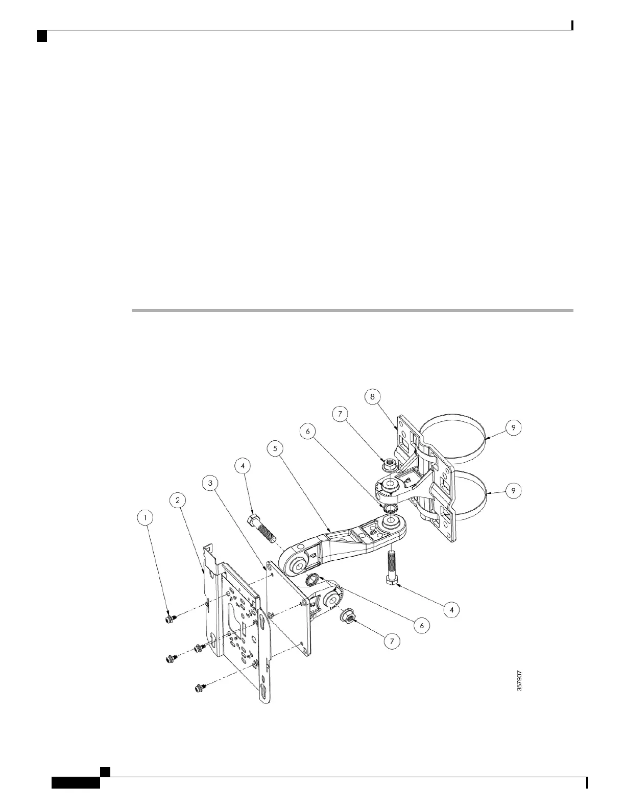
Mounting on a Pole or Mast Using Articulating Bracket
Figure 22: Exploded View of the Pole Mounting Articulating Bracket Hose Clamp Assembly
Cisco Catalyst Wireless 9166D1 Wi-Fi 6E Access Point Hardware Installation Guide
24
Installation Overview
Mounting on a Pole or Mast Using Articulating Bracket
 Loading...