EasyManuals Logo
Home>Cisco>Gateway>DPC3941T

Cisco DPC3941T User Manual

Cisco DPC3941T
80 pages
To Next Page IconTo Next Page
To Previous Page IconTo Previous Page
Page #60 background imageLoading...
Page #60 background image
Chapter 4 Operation of Front Panel Indicators
38 TP-00102
Initial Power Up, Calibration, and Registration (AC
Power applied)
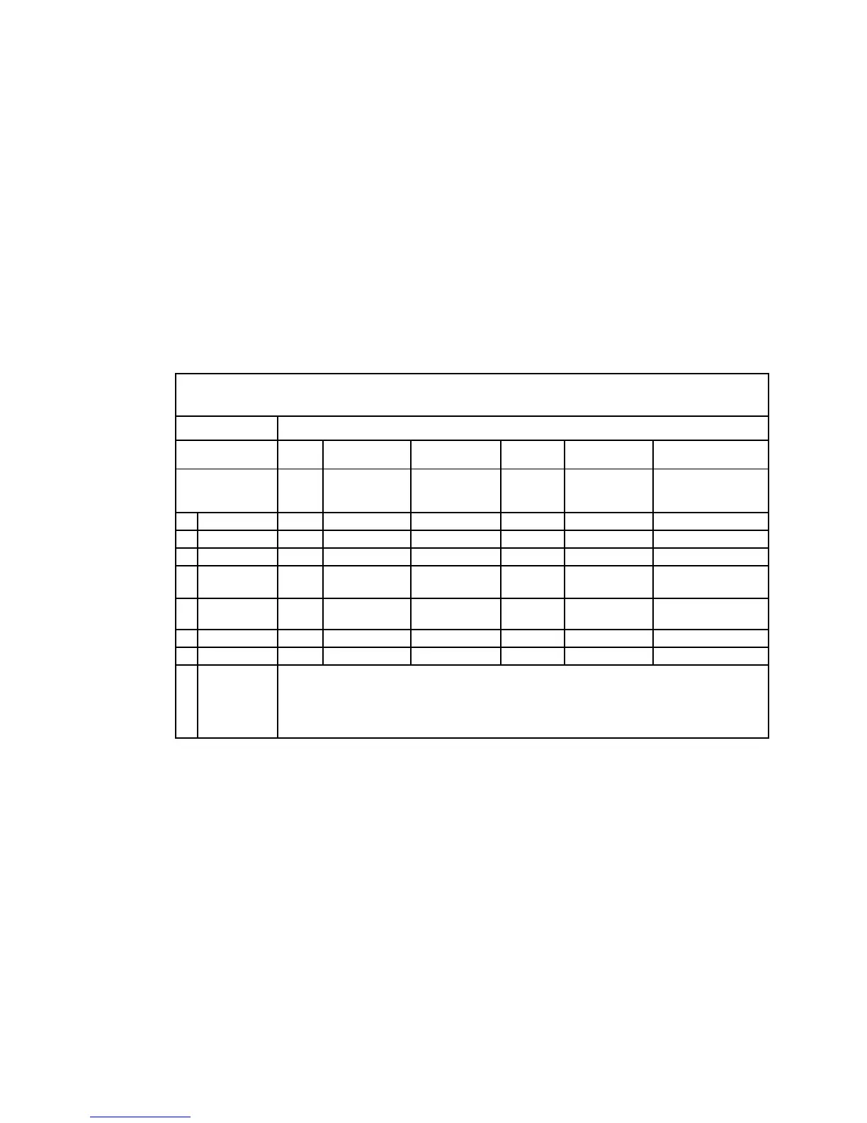
The following chart illustrates the sequence of steps and the corresponding
appearance of the Residential Gateway front panel LED status indicators during
power up, calibration, and registration on the network when AC power is applied to
the Residential Gateway. Use this chart to troubleshoot the power up, calibration,
and registration process of your Residential Gateway.
Note: After the Residential Gateway completes Step 7 (Data Network Registration
Complete), the Residential Gateway proceeds immediately to Normal Operations.
See Normal Operations (AC Power applied) (on page 40).
Front Panel LED Status Indicators During Initial Power Up, Calibration, and
Registration
Part 1, High Speed Data Registration
Step: 1 2 3 4 5 6
Front Panel
Indicator
Self
Test
Downstream
Scan
Downstream
Signal Lock
Ranging
Requesting IP
Address
Request High
Speed Data
Provisioning File
1
POWER
On
On
On
On
On
On
2
US/DS
On
Blinking
On
On
On
On
3
ONLINE
On
Off
Off
Off
Off
Blinking
4
2.4 GHz
On
On or Blinking
On or Blinking
On or
Blinking
On or Blinking
On or Blinking
5
5 GHz
On
On or Blinking
On or Blinking
On or
Blinking
On or Blinking
On or Blinking
6
TEL
1
On
Off
Off
Off
Off
Off
7
TEL
2
On
Off
Off
Off
Off
Off
8
BATTERY
On When battery is charged
Blinks When battery charge is low
Off When there is no battery in the unit

Questions and Answers:

Question and Answer IconNeed help?

Do you have a question about the Cisco DPC3941T and is the answer not in the manual?

Cisco DPC3941T Specifications

General IconGeneral
BrandCisco
ModelDPC3941T
CategoryGateway
LanguageEnglish

Related product manuals